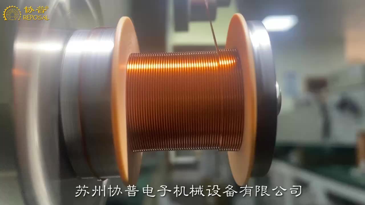
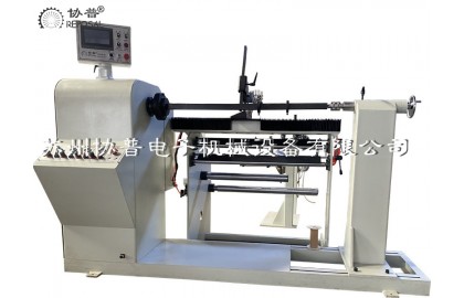
REPOSAL ® winding machine to overcome guidance fiber wire winding process difficulties
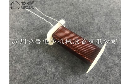
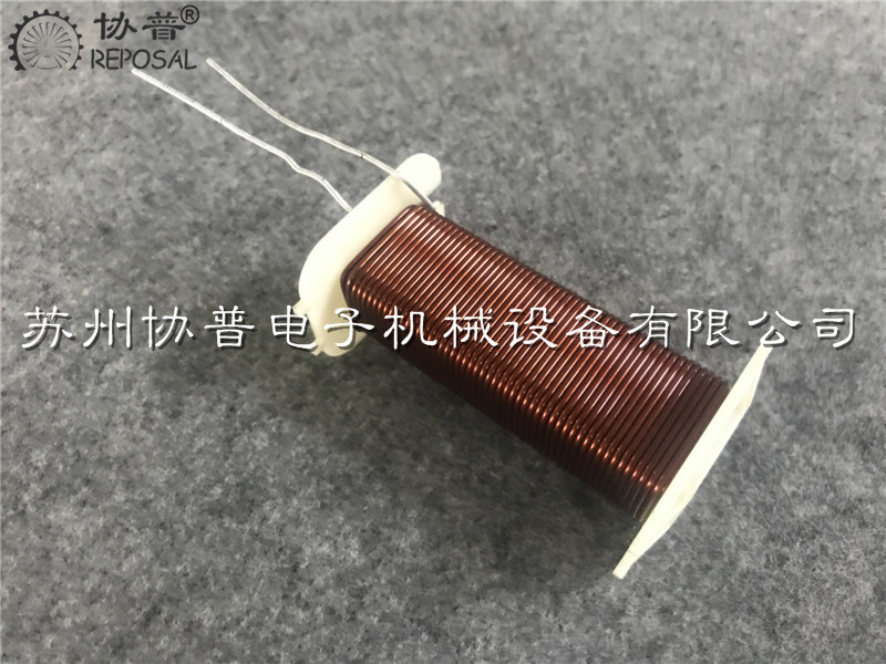
Optical fiber has many advantages, large communication capacity, long transmission distance, low fiber loss, anti-electromagnetic interference, no radiation, long life and so on, so it is widely used in the field of communication, especially. Guidance communication has an excellent application prospect, but the guided fiber wire package needs to be wound long distance without defects, but because the surface of the fiber is smooth, brittle and easy to break, as well as the residual stress generated by the micro bending will make the signal attenuation, so it is more difficult to wind than other fibers, making long distance fast fiber automatic winding without defects has become a major issue. REPOSAL® winding machine, as a professional winding process solution provider, has been developing process research on precision winding of guided fiber wire packages for many years. Good progress has been made and REPOSAL® special winding machine for guidance fiber wire wrap developed by the winding machine can set reliable process instruction information according to process requirements and accurately execute control commands to finally finish the long distance guidance fiber wire wrap without defects. In the whole research project, we focus on solving three problems of guidance fiber optic wire wrapping system: tension control. Winding system, feeder system, and expand as follows.
Tension control: optical fiber surface friction is very low, resulting in very easy to slide, and the fiber is brittle, easy to break; In the winding process, the optical fiber winding machine needs to be wound under constant tension, otherwise it is difficult to wind according to the pattern, which will generate residual tension in each turn. At the same time, in the process of winding layer by layer, the centripetal pressure between layers will be caused. The more layers, the compressive stress of the inner layer winding will be further increased. Will bring greater transmission loss. Therefore, the fiber winding process can only be controlled using the lowest possible tension. Therefore, tension control is crucial and very difficult in the whole winding process.
During the winding process of the optical fiber, entanglement and folding may cause damage to the optical fiber. Such damage may even lead to the inability to complete the winding. During the winding process of the optical fiber winding machine, the linear speed of the optical fiber winding should be kept as even as possible. This is also conducive to the stability of fiber tension. Optical fiber wire speed is determined by the spindle speed of the optical fiber winding machine, the spindle of the optical fiber winding machine is constant angular speed, but with the optical fiber layer by layer winding, in fact, the radius increases, so we must adjust the angular speed of the optical fiber winding machine according to the real-time radius to keep the linear speed of the optical fiber winding. The feed bobbin must adjust its own speed with the line speed around the bobbin (circular speed). Its linear velocity is also determined by its real time radius and angular velocity.
Through test analysis, it is concluded that different tension sizes have the following effects respectively. If the tension is too small, correct fiber winding cannot be realized. If the tension is too large, the residual stress is large, especially the interlaminar centripetal pressure, resulting in signal attenuation. Therefore, only the tension between the first two conditions, that is, a certain tension is required to achieve correct fiber winding, and as far as possible to the residual stress controller acceptable range.
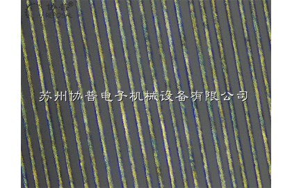
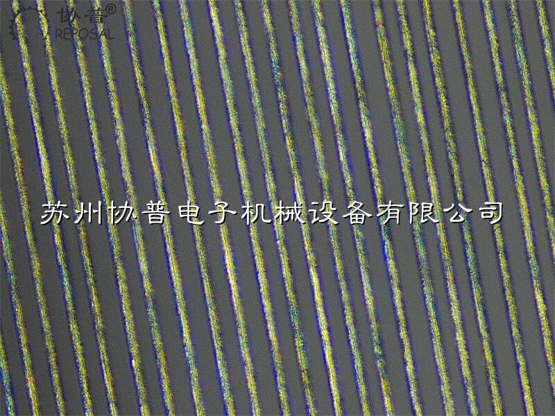
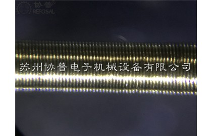
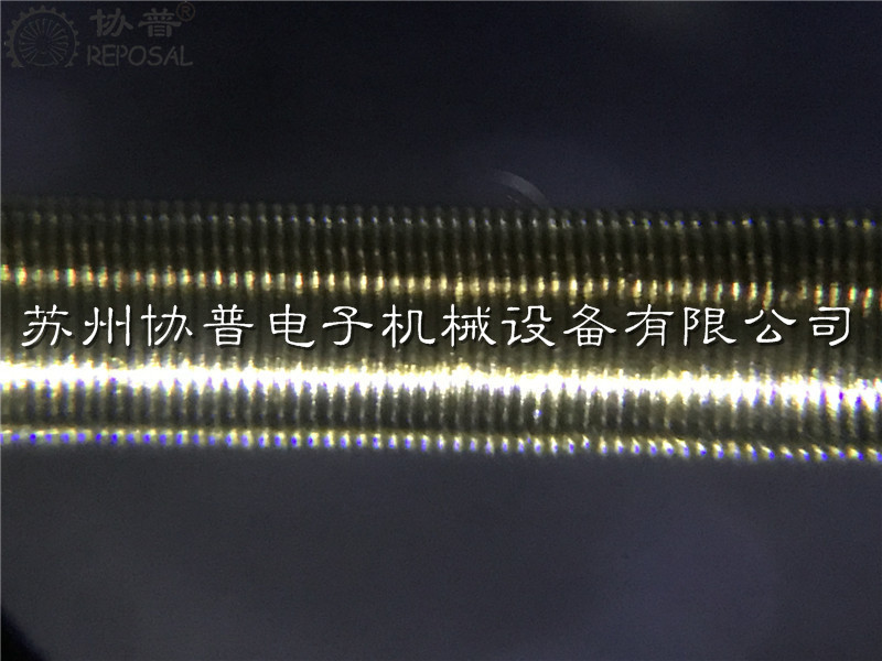
There is also the gap of fiber winding, that is, the gap between turns of fiber winding. Of course, the optimal situation is that turns are close to turns without gap or the gap is minimum. When the gap between turns of fiber is minimum, the next layer of fiber can be prevented from turning into the previous layer of fiber. At the same time, when the turns are close to the turns without gap or the gap is the smallest, it can also be conducive to the entire fiber winding layer smooth and flat, so that the winding of the second layer of fiber does not have micro-bending defects, but also can make the winding compact and the volume of the smallest.
But in the actual winding process, restricted by the optical fiber manufacturing process, the machinery of the optical fiber winding machine and the control accuracy, it is obviously impossible to do so. Our solution is to maintain a relatively constant lag Angle between the feeder point and the falling point during the winding of the fiber, and this lag Angle should be controlled within a relatively stable and reasonable range, and the lag Angle is too small. Then the turns are not tight enough and the gap increases. If the hysteresis Angle is too large, it will easily cause winding under the action of tension.
The hysteresis Angle is determined by two factors. The first factor is the position difference between the feeder point and the fall point in the axial direction. The second factor is the radial distance between the feeder point and the drop line.
The winding turns wind up the axis layer by layer, the winding diameter of the line increases layer by layer, and the distance between the feeder point and the falling line point also changes accordingly. Therefore, when we design the process, the feeder point needs to move backward accordingly according to the layer by layer winding.
The repeated winding test of optical fiber winding machine shows that the maximum lag Angle allowed to avoid the winding phenomenon is small and related to the tension. Under the condition of constant tension, the axial displacement accuracy is very high. We use AC servo motor to achieve this movement. The lag Angle can be acquired by Angle sensor, which can be used to control and adjust the position of the feeder point relative to the falling line point to obtain a stable lag Angle.
During the winding process, the drop point of the winding should be kept in a fixed position, generally at the top of the winding. Because the movement of the top point is actually a change in the winding speed, but in the actual winding process of the optical fiber winding machine, we will find that the falling line point will move layer by layer as an involute, there is a view that this is because in the case of constant angular speed around the spool, the fiber linear speed will increase the winding diameter in the process of winding layer by layer, resulting in the change of linear speed. However, the actual situation is that in the process of winding layer by layer, the falling line point is also the intersection point of the upper and lower layers. The height of this crossing point is higher than that of other guiding areas in the circumferential range. However, under the action of tension, the optical fiber will naturally slip from the height to the lower, so the falling line point of the layer by layer presents the involute line.
In order to ensure the stability of optical fiber winding, both ends of each layer should have a certain number of turns retraction maximum, generally 2-3 turns. This action is realized by the rapid acceleration of the winding axial motion. When the optical fiber is wound up, the winding glaze immediately rears back. Within one week of winding around the axis, it reverses the hysteresis Angle and then begins the second layer of winding.
Feeder section
Since the fiber winding machine can only use a low tension in the winding process, and the fiber on the supply coil is loosely wound, the tension changes greatly when the release. In order to eliminate this adverse effect and match the tension control system, the feeder part is designed as follows: the feed shaft is driven by a servo motor, and then the tension sensor dynamically adjusts the speed of the feed shaft in time according to the measured tension, so as to maintain a stable tension. Fiber tension, as the main parameter in winding process, is very important for long distance error-free winding of guidance fiber.
REPOSAL® winding machine as a professional winding process solution provider, Reposal ® winding machine has made continuous exploration and testing on the precision winding process of guided optical fiber wire package, cooperated closely with industry users, and successfully solved the above problems, which has been well received by users after in-depth cooperation.
Related Post
REPOSAL ® winding machine Honeycomb coil winding machine
REPOSAL® numerical control honeycomb winding
machine, specially designed for honeycomb inductor coil, honeycomb coil with
its small size, small distribution capacitance, and large inductance in some
special occasions has irreplaceable. All of these excellent properties are due
to the unique structure of the honeycomb coil,
Traditional honeycomb winding machine is to
rely on a set of complex gear system to achieve the function, if you need to
wind different honeycomb coils, need to manufacture and replace different
gears, quite cumbersome and very low efficiency, REPOSAL® CNC honeycomb winding
machine uses high-precision control system, with specific algorithms, high
precision, fast speed, through different Settings can be wound different
widths, different fold points, Different number of turns of honeycomb coil, let
you wind honeycomb coil handy.
The inductance of the honeycomb coil is large,
mainly because of its special structure. After it is wound, from the
appearance, it is like a honeycomb, formed by the regular winding of coils to
form a honeycomb, in this one honeycomb, the magnetic flux of each honeycomb is
interconnected, and the magnetic flux density of these small magnets changes
with the change of time and position, just like the food in a honeycomb. This
distribution of magnetic flux pores makes the inductance of the honeycomb coil
larger, because it has more magnet interaction, thus forming more magnetic
flux, improving the permeability of the current, making the inductance
increase.
At the same time, since the magnetic flux of
each small magnet in the honeycomb coil is interconnected, the inductance can
be increased by increasing the size of the honeycomb. The larger inductance of
the honeycomb coil is due to its shape and the distribution of magnetic flux
pores, rather than due to the increase in resistance.
The insulated wire wrapped around the honeycomb
coil can be a single strand of enameled wire, or can be multiple strands of
enameled wire or silk-covered wire.
People are usually curious about how this kind
of coil is wound out, and the following is a demonstration of the CNC honeycomb
coil winding machine developed by our company.
REPOSAL®successfully releases hot micro flowmeter winding machine
REPOSAL®successfully releases hot micro flowmeter winding machine
----------solve the problem of heat pipe coil winding process
Flowmeter is one of the commonly used instruments in industrial production, the most common such as all kinds of water meters in life, gear water meters, electromagnetic water meters, ultrasonic water meters, etc., according to the different industry applications, chemical, petroleum, pharmaceutical, food and other industries are also widely used, can measure the volume or quality of various fluids through the pipeline in a given time. Easy to measure in each fluid automation control.
However, in medical, aerospace, military and other fields, we may need to measure tiny fluid flows, and in microfluidic processes, micro-thermal flow meters are also necessary, which can measure very small fluid flows, thereby helping researchers control the flow of fluid in microfluidic devices and optimize device performance.
Another example is the flow control of pure oxygen fluid in the ventilator, the flow control of the medical dosage ratio, the flow equivalent is very small, and at the same time, it requires extremely high measurement accuracy, so the thermal micro-flow meter should appear according to demand.
The thermal micro flowmeter is mainly made of the principle of capillary heat compensation. In the thermal micrometer, the fluid passes through a small pipe, and on the outer wall of the pipe, the thermal micrometer winding machine is used to wind a very small electric heating coil, which usually uses a fine platinum resistance wire, with a diameter between 0.02 and 0.05mm. When the fluid flows through the platinum resistance heating coil, the temperature of the fluid increases slightly. At this time, another set of platinum resistance coils wound by the thermal micro-flowmeter winding machine can sense a higher resistance, and the controller converts this resistance value into a flow value.
The diameter of the platinum resistance coil in the micrometer is very small, and the texture is fragile, and it will heat up after being energized. When the fluid passes through the capillary of the flowmeter, the flow will take away the heat of the platinum resistance coil wound by the hot micro-flowmeter winding machine, resulting in a decrease in the temperature of the platinum resistance coil. In order to keep the temperature of the platinum resistance coil stable, the micro flowmeter will provide a certain current according to the measurement needs to maintain the temperature of the hot wire at a constant operating temperature. By measuring the change in current provided to the hot wire, the mass flow rate of the fluid can be obtained.
Thermal micro flowmeter has many advantages, the main advantage is high accuracy, can measure the flow range of small small fluid, the accuracy can usually be within 1%. Moreover, it is small in size and can be easily designed into module units for convenient arrangement. It can also directly output electrical signals, and the communication with the data collector is convenient.
However, its manufacturing difficulty is high, especially the platinum resistance heating coil, the need for hot micro-flowmeter winding machine, in a very small diameter capillary wound diameter 0.02-0.05 platinum wire, the small diameter of the platinum wire itself is more fragile, the capillary also needs to overcome the radial displacement caused by the tension of the platinum wire during the winding process, and requires orderly arrangement. The tension is stable and the resistance is consistent, so the process is extremely difficult, and the current micro-precision winding technology of this hot micro flowmeter winding machine has been supported by sensor companies in Japan, the Netherlands and Germany for a long time.
The domestic precision winding mechanism manufacturing system from low-end to high-end, there are huge challenges, because there are shortcomings in the manufacturing equipment link, not only the problem of individual equipment such as hot micro flow meter winding machine, but the entire precision winding machine industry is lack of independent development conditions, the industry is keen to imitate foreign industry technology for a long time, and the user long-term superstition imported equipment, It is also one of the conditions for domestic winding machine enterprises to lack independent development, so the cost of domestic thermal micro-flow meters has been high.
REPOSAL® winding machine has successfully provided competitive solutions to the electron microscopy winding process
The main components of scanning electron microscope are electron optics system, signal collection and processing system, vacuum system, image processing display and recording system, power system and computer control system. The core part is the electron optical system, which is mainly composed of electron gun, electromagnetic condenser, diaphragm, scanning system, astigator, objective lens and various centering coils.
Reposal® winding machine As a professional supplier of precision winding solutions, we focus on the electromagnetic condenser, objective and astigmatic, because the main components are enamoured wire windings, and the precision and consistency of the windings are highly related to the image quality of the scanning electron microscope.
Electromagnetic lens coil.
The electromagnetic lens is mainly used to restrain the electron beam and it can be regarded as a convex lens in optics. Because the electron beam in a rotating symmetric magnetic field will be subjected to the Lorentz force, resulting in a focusing effect. Therefore, the quality of the enamelled wire winding coil that can generate this rotationally symmetric rather than uniform magnetic field and make the electron beam focus imaging is very important.
The enamelled wire winding coil in the magnetic lens, when the current passes through the coil, the pole shoe is magnetized, and a magnetic field is established in the heart cavity, producing a focusing effect on the electron beam. There are two kinds of enamelled wire winding in the magnetic lens, namely, the enamelled wire winding of the condenser and the enamelled wire winding of the objective lens. The lens near the electron gun is the enamelled wire winding of the condenser, while the one near the sample is the enamelled wire winding of the objective lens. General condenser is the high excitation lens enamelled wire winding, high excitation lens enamelled wire winding has many turns, a cylindrical multi-layer arrangement, requires good rotation symmetry
Study on the control of the speed curve of the coiling machine for precision coiling machine
Your factory is using a traditional winding machine, your wire machine structure is reasonable, high mechanical accuracy, the motor is also used a big brand of motor, but in the winding of precision coils, there will be a high defect rate, you carefully analyze before improving various factors - equipment structure, processing accuracy, tooling accuracy, skeleton accuracy, enamel wire quality, tension control, etc. But it still doesn't solve the problem. But to tell you that it's not just a hardware problem, but an algorithm problem, may surprise you. Because in your opinion, every time the spool is transferred, the spool has a corresponding response, but in fact, you may not have considered that in the winding process of the precision coil, the wire guide pin is connected at both ends of the coil, and the sudden change in speed may cause the coil to cross the line and be raised. These defects can degrade the performance of the coil.
To solve this problem, we propose an acceleration and deceleration method based on 5-segment S-curve. The algorithm uses linear acceleration or deceleration at the end and end of the line motion control to help reduce coil defects. We first verify the feasibility of the algorithm by using ADAMS software. The software simulates the motion of the precision winding coil and obtains the velocity curve and displacement curve during the motion. Later, the experimental results show that the method of adopting S-curve in the alignment speed control can reduce the coil defect by up to 50%. This shows that the 5-section S-curve motion control algorithm is a promising method to improve the precision and efficiency of the winding process of electric precision coils. By using this algorithm, coil manufacturers can reduce the risk of coil defects and improve coil performance.
Winding machine is a special production equipment for precision winding coils. They can be divided into stator winding machine, flying fork winding machine, ring winding machine and flat winding machine according to the working mode and object. Different types of equipment are suitable for the production of different objects. For example, the stator winding machine is mainly used to produce motor stator coils, while the parallel winding machine is used to produce electromagnetic switching coils.
Ordinary algorithm of parallel winding machine in the production of precision winding coil products, although our mechanical structure, parts processing accuracy has been done very well, but often there is a problem of low wiring accuracy. In the process of winding a line coil, there are two main movements, one is the rotating movement of the skeleton, which is called winding movement, and the other is the translation movement of the guide needle, which is called wiring movement, and wiring transport is matched with winding movement. After years of technical accumulation, we analyze that the leading role in the alignment accuracy is the alignment movement of the guide needle. Therefore, if you want to improve the alignment accuracy of the coil, you need to optimize the alignment movement of the guide pin.
In fact, we have always believed that the winding machine is equivalent to the lathe in the electrical industry, its importance is self-evident, so for its accuracy, there have been many experts and scholars to study this.
Some people studied the mathematical model of precise alignment based on axial pressure compensation around the axis in the process of alignment. The axial pressure was used to improve the alignment regularity of the coil, and the mathematical model was established according to the analysis of the end point of the coil alignment, which improved the alignment accuracy of the coil.
Some people use the 5-section S-curve control algorithm and the 7-section S-curve control algorithm respectively in the research. In motion control, the 7-section S-curve is more complicated than the 5-section S-curve control. This method has achieved more results in the field of CNC machining, but it is not mature in the field of winding machine.
The tension instability caused by the friction between the enamelled wire and the conductor nozzle during coil winding has been studied, which leads to the uneven wiring of the coil and the breakage of the enamelled wire.
Some people have studied the low efficiency of the winding machine in the traditional winding control because of the inertia error in the process of the winding machine. Instead, the servo motion wiring and the inertia error supplement are used to improve the control efficiency of the winding machine.
PLC control is commonly used in the winding machine wiring control system, through PLC control servo motor can realize the winding machine wiring control, both PLC control stability and high precision servo motor advantages. However, there is a sudden impact of guide pin speed in the coil alignment of parallel winding machine, so it is necessary to further optimize the change of guide pin running speed to improve product quality and the smoothness of wire alignment speed. The S-curve algorithm is a kind of smooth transition of speed in the process of motion, which is often used in machining to solve the problem of breaking the tool caused by speed impact and improve the precision of machining products. In the winding machine, the speed of the guide needle can be changed into an arc smooth transition by controlling the movement track of the guide needle, improving the alignment accuracy and product quality.
To sum up, an algorithm based on 5-segment S-curve motion control is proposed to solve the problem of velocity shock in the process of coil alignment by analyzing the law of coil alignment. ADAMS software is used to simulate the trajectory of the guide pin to verify the feasibility of the algorithm. And the application of the example proves that the 5-section S-shaped curve can effectively solve the phenomenon of crossing and protruding in the process of winding, and improve the precision of winding.
Coil wiring principle
The winding method is flat winding, that is, the enameled wire moves synchronously with the guide pin and always keeps perpendicular to the skeleton during winding. The frame is driven by the winding motor with the guide needle movement, the enameled wire is wound on the skeleton, in which the guide needle is located in the wiring arrangement mechanism and the winding mechanism are two independent mechanisms. The winding mechanism is divided into three stages according to the motion process of the guide pin, namely acceleration and deceleration stage, uniform speed stage and end point return stage. The acceleration and deceleration stage can be divided into two parts: acceleration stage and deceleration stage. In the early stage of the alignment movement, the guide pin speed from zero to uniform speed belongs to the acceleration stage. At the end of the alignment movement, the process of decelerating until the speed reaches zero is a deceleration stage. The middle constant velocity stage is the constant velocity motion stage of the guiding needle. The terminal reentry stage is a process in which the guide needle accelerates backward again after slowing down and stopping. Here we explain:
Acceleration and deceleration stage
In order to arrange the lines evenly, the two movements of guide pin movement and skeleton rotation should meet certain coordination relations during acceleration and deceleration stage. The time for the guide needle to move one diametral width distance must be equal to the time for the skeleton to rotate once, that is, the guide needle to move just one diametral distance when the skeleton rotates once.
REPOSAL® Winding machine Optimum design of CNC winding machine for large power transformer
In the manufacture of power transformers, winding the transformer coil is a super important step, you think, the transformer coil is wound more firmly and neatly, the strength of the transformer and the ability to protect against short circuits can be greatly improved. However, most of the current transformer winding machines have to rely on manual extra sorting of the coil, the entire equipment is low in automation, and the production efficiency is not high, so the development of an excellent large transformer winding machine is a crucial thing for our company.
![]()
We have studied the main shaft technology of transformer winding machine, the relationship between compaction force and winding quality, and the control of compaction force. According to the principle and process flow of transformer winding, we put forward a whole design scheme of large transformer winding machine, including mechanical structure and electrical control. Mechanically, we simplify the complex structure of traditional transformer winders. In terms of electrical control, we ensure the stability of the motor when it starts and stops, and ensure that the winding coil is evenly tightened during the winding process. For the core parts of the transformer winding machine, spindle system and pressing device, we have calculated and selected the types and parameters. With the compaction device, we are able to provide real-time axial and radial compaction forces during the winding process of the transformer winding, which is very effective for improving the tightness of the winding.
The static analysis of the radial compaction device of the winding machine is also carried out by using finite element method, and the structure optimization is carried out according to the analysis results. We find that as the number of layers and turns of the winding increases, the required axial and radial compression forces change accordingly. By analyzing the experimental data, we find that there is a maximum value and a minimum value in the range of quality requirements, and it is the most reasonable choice to make the compression force approximately proportional to the number of layers and the number of turns.
The large transformer winding machine developed by our company has been preliminatively debugged and put into the market. After testing, the performance parameters of this transformer winding machine are in line with the design requirements, and the operation is stable and efficient. It can be wound to make a tight and regular transformer winding coil, and has been fully recognized by the market.
As a power grid equipment, power transformer converts voltage through the electromagnetic induction between the winding coils of the transformer. With the continuous development of the market, higher requirements are put forward for the manufacturing level of transformers, and the market needs more energy-saving and efficient transformers. Therefore, the optimization of the transformer manufacturing process is particularly critical. Quality and performance depend on the process equipment. The technical level of the transformer winding machine directly reflects the manufacturing level of the transformer. Therefore, accelerating the development of transformer winding machine is an important guarantee to improve the performance of transformer.
![]()
The winding coil of the transformer is the core component of the transformer and constitutes the electromagnetic induction part of the transformer. It generally includes high voltage winding and low voltage winding, respectively connected to the high voltage grid and low voltage grid. The winding of large power transformers usually adopts concentric winding, that is, the high and low voltage transformer winding coils are centrally set on the core column. The manufacture of transformer winding is the core process of transformer, and its quality plays a crucial role in the performance of transformer, affecting the appearance of transformer size, weight, mechanical properties, insulation and heat resistance and other important indicators.
In the past, the production of transformer winding coils relied on manual, and workers had to wind insulated wires manually to the winding die frame in accordance with the process requirements. Turns calculation also have to rely on manual, this old-fashioned method is inefficient, and because the worker's skills are not strong enough, the quality of the winding coil is poor, the number of turns may be miscalculated or missed, and ultimately lead to the finished winding coil performance can not be guaranteed. Later appeared semi-automatic transformer winding machine, which is driven by the motor to rotate the spindle to wind the transformer winding coil, although it improves the production efficiency, but the wiring work still has to rely on manual, only suitable for flat winding transformer winding coil winding, and winding head winding, welding and other operations must still be completed manually, so the product quality is not stable.
Later, with the emergence of TTL logic gate circuits, in the mid-1970s, with the development of CMOS technology, various types of equipment program control a large number of applications of digital integrated circuits, Western countries and Japan and other industrial powers have emerged CNC winding mechanism manufacturing industry. These CNC transformer winding machines represent the advanced level of winding mechanism manufacturing technology, especially the winding equipment produced in Japan, Italy, the United States and Germany is the leading technology.
Now the transformer winding machine as the core parts of the transformer production equipment, the market demand is very large, and the transformer manufacturing enterprises at home and abroad attach great importance to the development and application of advanced technology of transformer winding machine. Domestic transformer winding machine production enterprises are small, insufficient technical reserves, limited research and development funds, so there is still a big gap compared with foreign advanced products, the market share is low, unable to compete with foreign countries. To solve the key technical problems of transformer winding machine is the key to improve the quality of domestic winding equipment and enhance the market competitiveness. In order to meet the demand of transformer manufacturers for high quality and low price winding equipment, especially large transformer winding machine, on the basis of learning from foreign advanced experience, combined with domestic research results, the development of large transformer winding machine has important significance and practical value.
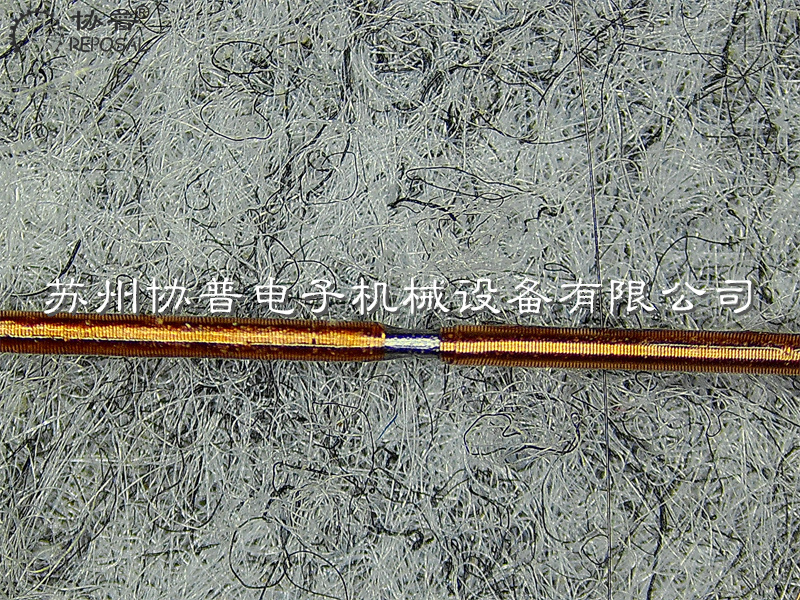
REPOSAL® winding Machine successfully overcomes the polarization grid precision winding technology
Since these polarized wire grids, which are wound by precision winding machines, have no underlying substrate, they have the advantage that they are not affected by substrate related dispersion and absorption, and there is no beam deviation during transmission. This provides a thin, compact and versatile polarization element with a high degree of polarization over a wide transmission range.
At present, because there is no professional winding machine, most of the polarization grid used in our country is imported polarization grid, and the price is expensive; However, the domestic processing method of wire grid mainly uses manual winding, which has low precision and long production cycle. At the same time, the winding machine at home and abroad is mainly used in electronic components, sensors, etc., the control variable is relatively single, and the main control mode is tight layout, even the high precision winding machine, there are few equal spacing layout for the polarization line grid, so the accuracy can not meet its needs. Therefore, it is very important for the coiler to overcome the polarization grid precision winding technology.
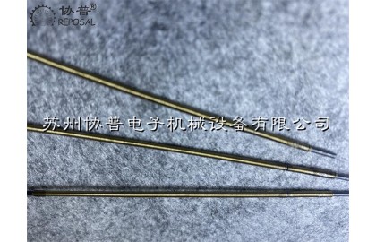
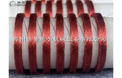
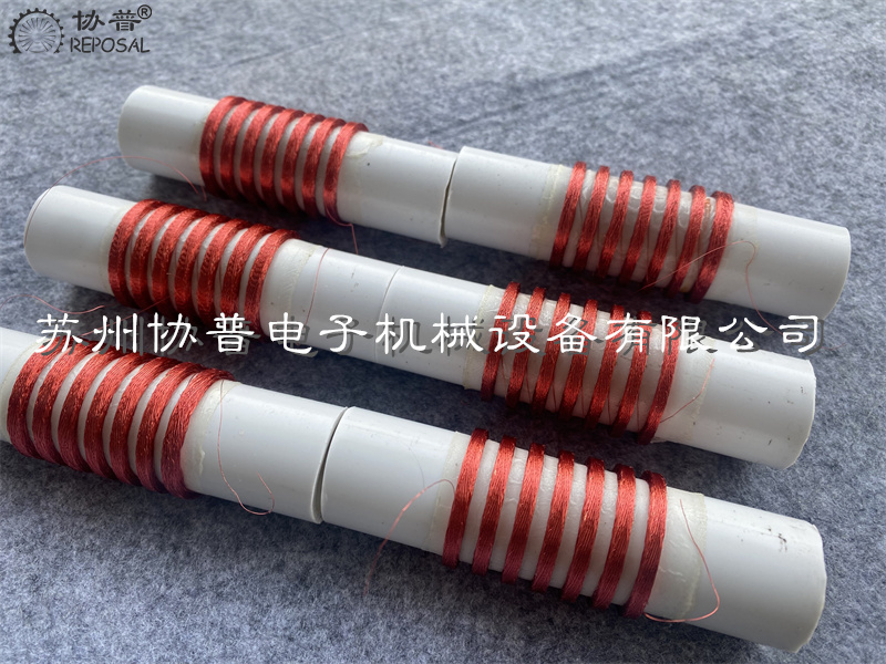
REPOSAL® has successfully released a radiofrequency ablation catheter winding machine
Radiofrequency ablation has ablation and cutting functions, and the main therapeutic mechanism is thermal effect. Radio frequency refers to radio frequency, frequency up to 150,000 times per second of high frequency vibration, but it does not belong to the division of bands in radio communication.
The coiling process is completed by continuous test and optimization of the coiling machine.
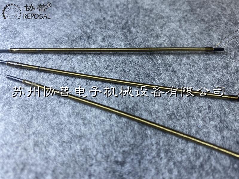
The working flow of this winding machine is as follows:
1. The active wire feeding device of the radiofrequency ablation catheter winding machine ensures that the wires are constantly connected and not tied.
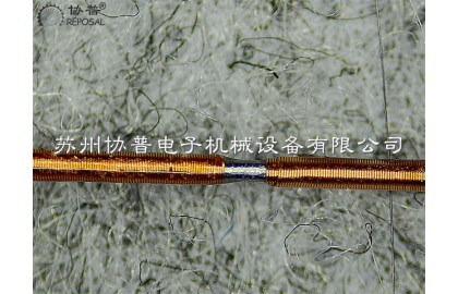
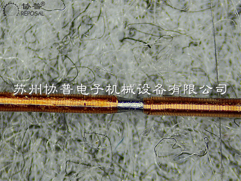
2. Double fold section A measurement line.
3. Manual folding head.
4. Manually fix the thread head (Two schemes are tentatively proposed for fixing the thread head)
4.1 Fix the starting position with glue. The fixture locks the PEEK tube.
4.2 Kangtong wire is hung on the feature of steel pipe. Glue to fix the ends after wrapping.)
5. Press the start button of the radiofrequency ablation catheter winding machine to wrap.
6.(During the winding process of the radiofrequency ablation catheter winding machine, both AB and AB segments have adjustable tension)
7. Wrap the jump grid to the specified position (the specific hop length can be set, and the rotation Angle can be set.
8. After the radiofrequency ablation catheter winding machine is finished, the feeder stops at the end and maintains tension.
9. Fix the end of the line by manual dispensing
10. Both ends of the radiofrequency ablation catheter winding machine are coaxial, and the rotation direction is synchronized.
11. Adjustable pre-drawing force is required at both ends of the locking shaft core.
Precision Winding Machine | Hollow Coil Winding Machine | Whole Column Coil Winding Machine
Precision winding machine
Precision winding machine For general winding machines, including CNC and automatic winding machines, only the set number of turns of enameled wire is required to be wound, and the appearance is roughly flat, but there are some special high-demand occasions , It is required that the arrangement of enameled wires must be neat without a random winding.
This kind of coil has several advantages. First, the consistency of inductance is very high. Second, the enameled wire occupies less space, and the enameled wire can reach the ideal neat arrangement. Third, the energy density is high. Fourth, the high temperature resistance performance is better. , The enameled wires are in line contact, and in the case of random winding, the superimposition between the wires will have a little contact, and it is easy to break down under high temperature and high pressure.
In order to achieve a stable and neat arrangement, in addition to the requirements for enameled wires, compared with general coil winding machines, high requirements are put forward for the electronic control, mechanism design and manufacturing accuracy of structural parts of the fine winding machine.
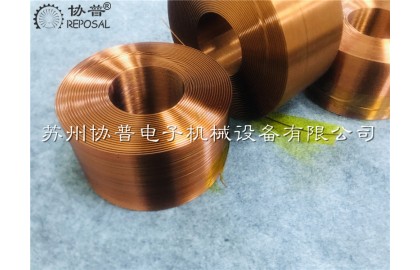
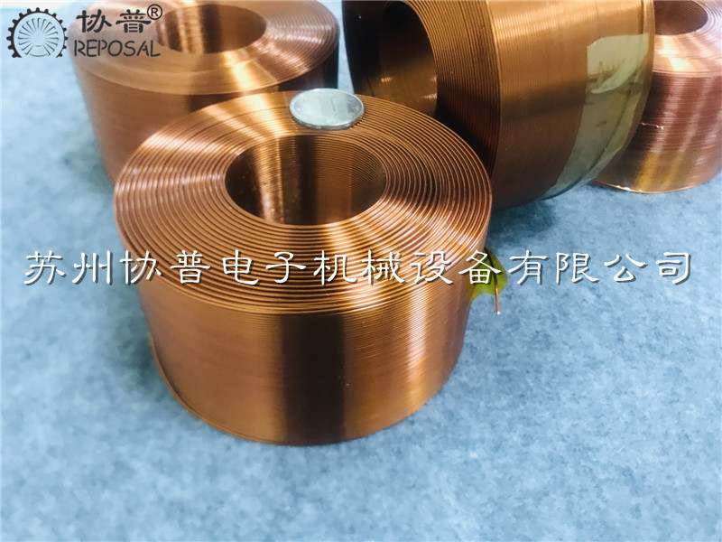
REPOSAL® winding machine releases special winding machine for frequency divider inductors
REPOSAL® winding machine releases special winding machine for frequency divider inductors
In daily life, have you ever noticed more than one horn on your car? And more expensive cars have more horns. According to normal people's thinking, the car as long as there is a horn can emit sound signals on the line, more horn is why? The reason is very simple, for example, the turn signal and the warning horn are completely different, the sound frequency is different, and the sound range of the speakers used for high and low is naturally different. A single speaker cannot play a full frequency sound, and a sound may require a combination of multiple channels of sound to achieve a clear cue.
Therefore, in order to make each speaker emit audio suitable for it, it is necessary to use a tool such as a frequency divider. In simple words, the frequency divider is a filter circuit composed of a capacitor and a frequency divider inductor coil wound by the frequency divider winding machine. The capacitor filters the low frequency to the tweeter, and the frequency divider inductor is wound by the frequency divider winding machine to filter the high bottom to the low frequency to the woofer, so as to distinguish the sound signals in different frequency bands in a sound. It has different sound frequency channels, high frequency sound channels can only pass high frequency sound, middle and low frequency sound the same. After the sound is distinguished, the sound is amplified and played in the corresponding sound amplifier, and finally we can get the most accurate audio we want.
Frequency dividers are divided into two categories, one is a power divider, and the other is an electronic divider.
The power divider is set in the speaker, the power amplifier in the speaker first amplifies the sound power, and then the power divider divides it into three audio signals, high, middle and low, and finally sends it to different speakers for playback. The advantage of this power divider is that it is simple and convenient to connect and use, but its disadvantages are also obvious, that is, its power consumption is large and the parameter deviation value is large, the error of the sound frequency is large, and its error is related to the impedance of the speaker, so it is not convenient to adjust.
REPOSAL ® winding machine has successfully realized the coil preparation process of the frameless capillary magnetic liquid acceleration sensor
In particular, the non-magnetic material in the magnetic liquid will be subjected to a magnetic field force in the non-uniform magnetic field, which makes many magnetic liquid acceleration sensors can be designed based on this characteristic.
These characteristics make the magnetic liquid acceleration sensor has many advantages compared with the traditional acceleration sensor, such as no wear, high sensitivity and simple structure.
However, most of the existing magnetic liquid acceleration sensors use solid mass blocks as non-magnetic substances, and use coils to detect changes in inductance under different accelerations to obtain output signals. However, its disadvantage is that it leads to complex magnetic circuit and poor sensor stability.
A new solution emerged -- the capillary magnetic liquid acceleration sensor, good stability, simple magnetic circuit, accurate and reliable measurement results and long service life.
Research and development of horseshoe hollow cup motor coil and winding machine
Research and development of horseshoe hollow cup motor coil and winding machine
In recent years, China has paid more and more attention to hollow cup motor and automatic winding technology, and has made good progress and breakthroughs in the research and development and manufacturing of winding machine equipment.
One of the key reasons for the impact on the performance of the motor is the rotor coil in the motor, the rotor in the hollow cup motor has no iron core, small inertia, excellent functionality and a wide range of applications. In addition, in the research and development of coil winding equipment, the saddle-shaped coil arrangement is regular, and the utilization efficiency of magnets is high.
Compared with the old traditional motor with an iron core, the energy conversion efficiency is significantly higher than the latter, and the reaction speed will be much faster, and the hollow cup motor has high efficiency, fast response speed and stable performance. Because the hollow cup motor has no lag, additional electromagnetic interference is low, very high motor speed can be achieved, and the speed setting is sensitive at high speed, so it has relatively stable and stable performance. In addition, the energy density of the hollow cup motor is much greater than that of other motors, and the weight will be much less than that of an iron core motor with the same power.
Now according to the forming method of the coil, in the hollow cup motor coil, its production technology can be roughly divided into two process routes: winding production technology and one molding production technology.
Compared with the two methods, the first winding production technology is more complex, and the efficiency of winding the coil is relatively low. In order to improve the winding efficiency of coil production, the winding machine can be added to the production process of one molding. According to the hollow cup coil shape and winding method, the common hollow cup winding method can be divided into three kinds of parallel straight winding, saddle winding and oblique winding. The first parallel straight winding is generally used for hollow cup motor winding with relatively few turns. The last two are the two coil winding processes commonly used by the relatively advanced hollow cup motor manufacturers abroad.