Detailed explanation of the operation instructions of the transformer winding machine
Detailed explanation of the operation instructions of the transformer winding machine
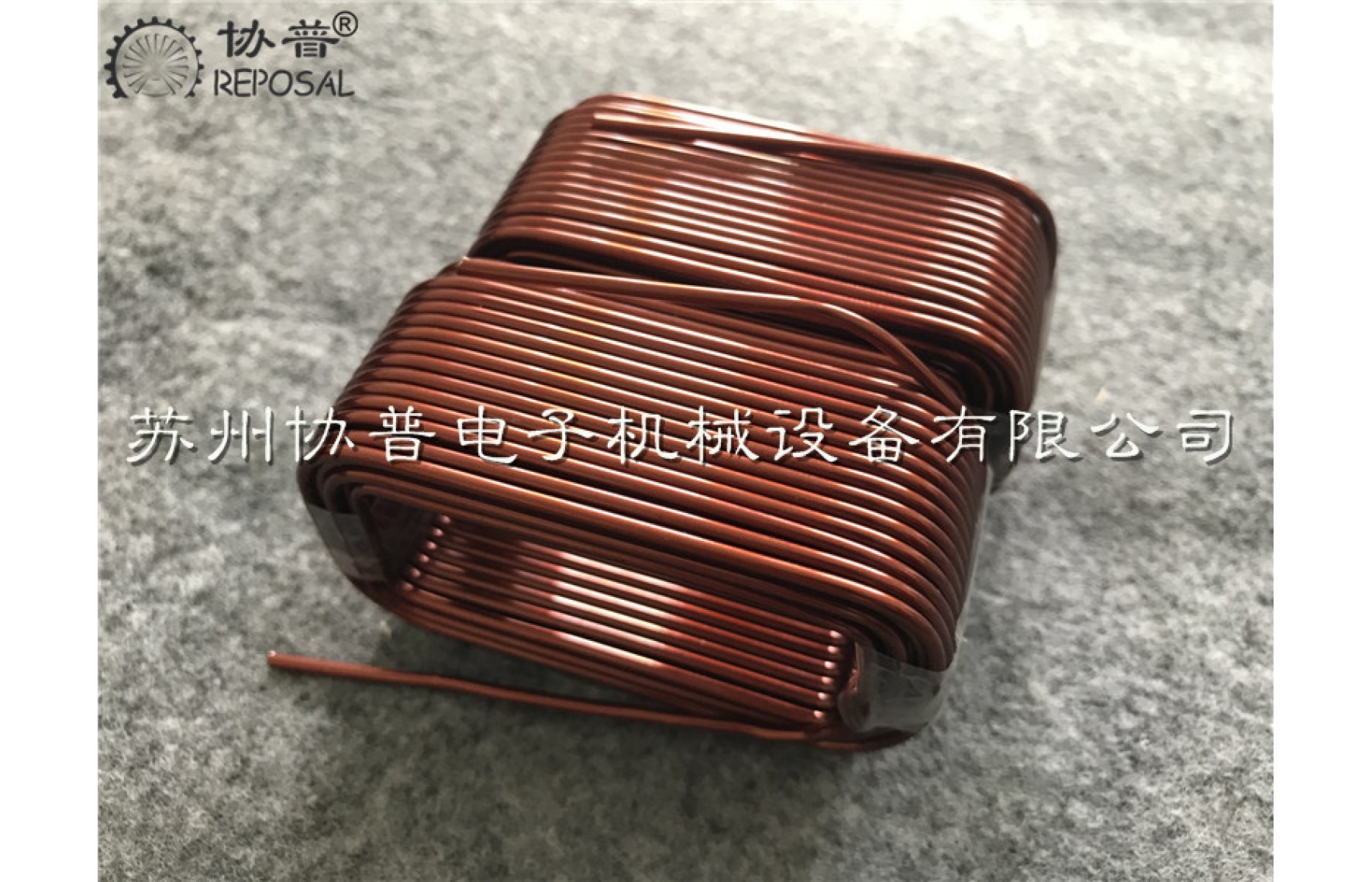
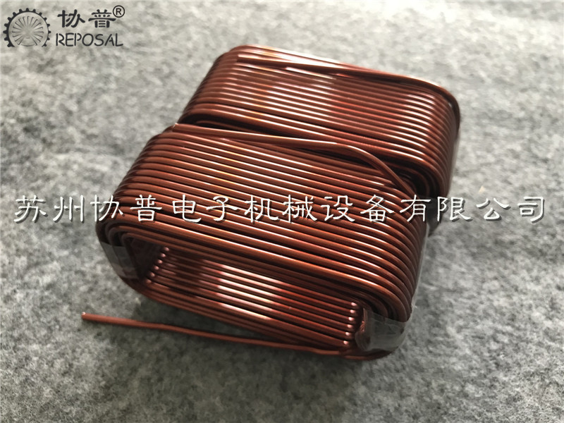
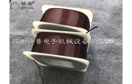
Transformer winding machine is a special winding equipment for winding enameled coils of transformers. During the winding process of enameled coils of transformers, winding enameled wire equipment is divided according to the specifications of the transformer. Enameled wire winding machine and foil enameled coil winding machine; there are vertical winding machines and horizontal winding machines for winding enameled coils of large power transformers.
1. Structural characteristics of transformer winding machine:
1. The mechanical transmission part of the winding machine is located inside the headboard, and the electrical part is installed on the top of the headboard. The three-phase asynchronous motor is driven by the frequency converter to realize the linear change of the spindle speed.
2. The winding machine adopts stepless speed regulation, and the controller outputs 0-10V analog voltage, which is connected to the inverter. By means of percentage, there are a total of 100 gears, which can be counted accurately, and can also be counted in reverse to automatically stop.
3. The winding machine can count reversibly, and is equipped with an electromagnetic brake device to prevent reversing when winding the enameled wire to stop, and ensure that the automatic counting will not produce errors. If you need to manually reverse, you can manually press the brake button to release, and the manual rotation can also count.
2. Safety operation rules for transformer winding machine:
1. Equipment and utensils:
Winder and shelf for fixing enameled wire reels.
Enameled wire winding jig and baffle plate corresponding to the product.
Scissors, wrenches, needle nose pliers, wooden hammers and other tools.
Corresponding coil processing drawing files.
2.Material:
Double glass filament enameled wire or enameled enameled wire that meets the requirements of coil processing drawings.
Skeleton plate
insulating film paper
ventilation strip
white gauze
Glass cloth tape
Insulated conduit
transparent adhesive tape
3. Winding process:
Enameled wire winding jig, enameled wire, insulating film paper and ventilation strips and other materials prepared according to the coil processing drawings. Check the winding machine before use: whether the forward rotation, reverse rotation, etc. are normal. If you have any questions (especially the specifications of enameled wires), you should report to the person in charge of the winding department in time, and ask the winding department to confirm. Enameled coils are divided into enameled coils and double enameled coils. The winding methods are quite different and should be carried out according to the following methods:
Third, the winding method and steps of the transformer winding machine:
Install the winding jig, baffle plate and skeleton plate respectively, and tighten them with a wrench. Tightly wrap 3 turns of insulating film paper with the same length as the winding jig on the outside of the skeleton board. Stick with clear sticky tape so it won't come loose. Pass the enameled wire head through the baffle and reserve the length of the enameled wire head as required, and wear an insulating conduit suitable for the enameled wire gauge. Make sure the conduit does not slip out of the enameled coil. The length of the conduit outside the baffle should not be less than 60mm.
For enameled coils with end taps, the end taps shall be carried out according to the order of the coil processing drawings, and the end taps shall be arranged in sequence, with special attention to the accurate number of turns; the conduit guides the two enameled wires with the end taps in At the same time, and directly lead to the root of the tap at the end, leave a conduit of more than 60mm on the baffle, and reserve the length of the enameled wire from the tap at the end as required. In order to ensure that there is no inter-turn short circuit at the folded enameled wire at the end of the enameled wire, two layers of glass cloth tape or polyester insulating film should be wrapped at the folded enameled wire.
If the coil processing drawing requires that the enameled wire gauge should be replaced at the position of the tap at the end, the large enameled wire with the enameled wire drawn from the tap at the end should be longer than the small enameled wire, and the size of the enameled wire should be consistent with the coil processing drawing. If there are joints in the winding, they are used as external types within 8mm, and they are cut 80mm outside the baffle.
The ventilation strips should be placed on the four corners of the enameled coil. Put the ventilation strip on it, and after winding it for a few turns, hit it with a wooden hammer on both sides of each four corners of the enameled coil, so that the ventilation strip will not slide, and then continue to wind the enameled wire. When winding the secondary enameled coil (coupling enameled coil), first wind the primary enameled wire. After the primary enameled wire is wound, level it first, then wrap three and a half layers with polyester insulating film and stick the seam with transparent tape. Pad up around the secondary enameled wire to electrically isolate the primary enameled wire from the secondary enameled wire. The closest distance between the two enameled wires is not less than 3.5mm to be considered qualified around the enameled wire.
When the enameled coil is wound for the last few turns, a cable tie (white gauze tape or conduit) should be placed to facilitate the tightening of the enameled wire tail, and the cable ties should be fastened at two positions respectively. The enameled wire tail should be led to the insulating conduit in the same way as the enameled wire head. After the enameled coil is wound, level it, then remove the enameled coil and demould, cut off the excess head of the cable tie, and place the enameled coil in the designated position. The storage location should be protected from moisture and dust.
Fourth, the winding method and steps of the double enameled coil of the transformer winding machine:
The grouped enameled coil has more than two enameled coils, and the two enameled coils are connected in series. For this enameled coil, the total length of the enameled wire that needs to be used for the enameled coil should be calculated first, and the enameled wire should be removed from the plate and cut.
Install the baffle plate and the winding jig, start winding the first coil, take off the enameled coil after winding, turn it tightly at the four corners, and then install the enameled coil on the winding machine in the opposite direction, and start winding the first coil. For the second plate, the same method can be used to wind the third plate. The enameled coils with more than three coils are generally divided into two groups and wound separately. After winding, they are connected in series and combined into a group of enameled coils. After the enameled coil is wound, cut off the excess head of the enameled wire, and store it in the designated position after flattening.
Related Post
REPOSAL® machine for radiofrequency ablation catheter
The precise winding process ensures the efficient transfer of energy, thereby improving the efficiency and consistency of ablation. The uniformity of the precision wound coil affects the temperature distribution of the ablation area, avoiding local overheating or heat deficiency, which is essential to ensure the ablation effect and reduce complications. The stability of the winding process ensures the reliability of the operation. The high-quality winding process withstands stretching and bending during surgical operations, reducing the risk of breakage or functional failure. High-quality winding processes have a longer service life and are able to maintain stable performance through multiple operations, thereby reducing medical costs and improving resource efficiency. The quality of the winding process also affects the precise control of the ablation process. The high-precision winding process helps physicians to more precisely control the size and shape of the ablation area to achieve optimal treatment results.
Moreover, the RFA catheter winder is designed with operational safety in mind, reducing potential risks during operation and protecting operators and products from damage. It can adapt to different types of radiofrequency ablation catheter production requirements, and has good flexibility and scalability. The structure and design of special winding machines are often more simplified and easier to maintain and maintain, thus reducing long-term operating costs.
The advantages of radiofrequency ablation catheter winding machine are mainly reflected in professional design, high efficiency production, precise control, quality stability, easy operation, material saving, safety, strong adaptability, low maintenance cost and technological innovation. These advantages make the radiofrequency ablation catheter winding machine an indispensable key equipment in the production process of radiofrequency ablation catheter.
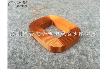
EI84 transformer coil winding machine
EI84 transformer coil winding machine
REPOSAL's successfully developed precision flexible Roche coil winding machine
Precision Flexible Roche Coil Winding Machine is a special equipment for winding precision flexible Roche coils. With the actual project as the background, Xiepu successfully developed a precision flexible Rogowski coil winding machine by decomposing the flexible Rogowski coil winding process.
The precision flexible Roche coil winding machine does not belong to the ranks of general numerical control equipment, but a special non-standard equipment. For this type of equipment, it is mainly reflected in a special purpose. Since the special purpose means that the market demand is not large, it is indispensable. For equipment manufacturers, the development of such special equipment is not favored, and cost control is very difficult.
In addition, the current domestic manufacturers of flexible Roche coils have limited demand for equipment. At the same time, if you want to control the pitch accuracy and alignment, the equipment research and development costs are relatively high, and the market risk is large. At the same time, for equipment users, their corresponding The supporting equipment and instruments are a large investment.
REPOSAL successfully developed string winding machine
REPOSAL takes the string winding machine as the research object and adopts the modal analysis method. Firstly, the vibration principle and the movement principle of the winding mechanism of the small string winding machine are discussed in theory. Based on the principle analysis, the vibration analysis of the ADAMS model of the small copper wire winding mechanism to study the vibration damping characteristics between the roller shaft and the frame is carried out respectively, and the wire winding mechanism of the string winding machine is made using ANSYS software. Modal analysis was carried out for normal operation. Through analysis, the vibration characteristics of the winding mechanism of the string winding machine under normal working conditions are obtained respectively to optimize the vibration damping measures of the winding mechanism. At the same time, the mechanical characteristics of the thin wire and CNC under the normal working state of the CNC winding mechanism are analyzed. , Optimizing the feasibility of applying the CNC cable winding mechanism to the string winding machine cable winding mechanism.
Enameled wire production process
Enameled wire technological process: pay-off→anneal→paint→baking→cooling→take-up
1. Pay-off On a normally operating enameled machine, most of the operator's energy and physical strength are consumed in the pay-off part. The replacement of the pay-off reel makes the operator pay a lot of labor, and the joints are prone to quality problems when changing the line. An operating failure has occurred. An effective method is to pay off with large capacity.
The key to pay off is to control the tension. When the tension is large, it will not only draw the conductor thin, make the surface of the wire lose its brightness, but also affect many properties of the enameled wire. From the appearance point of view, the enameled wire that is drawn thinner has poor gloss; from the performance point of view, the elongation, resilience, flexibility, and thermal shock of the enameled wire are all affected. If the pay-off tension is too small, the line will easily jump and cause the line to be merged and the line to touch the furnace mouth. When paying off, the most fear is that the half-turn tension is high and the half-turn tension is small. This will not only cause the wires to loosen, break, and be thinned section by section, but also cause large jumps of the wires in the oven, resulting in failures of merging and touching the wires. Pay-off tension should be even and appropriate.
Installing a booster wheel in front of the annealing furnace is very helpful for tension control. The maximum non-extension tension of soft copper wire at room temperature is about 15kg/mm2, the maximum non-extension tension at 400℃ is about 7kg/mm2; the maximum non-extension tension at 460℃ is 4kg/mm2; the maximum non-extension tension at 500℃ The extension tension is 2kg/mm2. In the normal enameled wire coating process, the tension of the enameled wire is significantly less than the non-extension tension, which is required to be controlled at about 50%, and the pay-off tension should be controlled at about 20% of the non-extension tension.
Special miniature permanent magnet trip coil winding machine
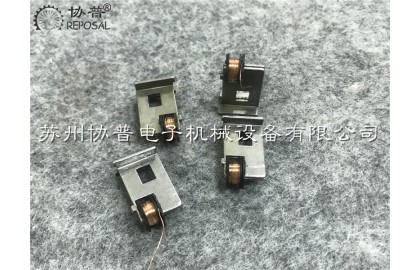
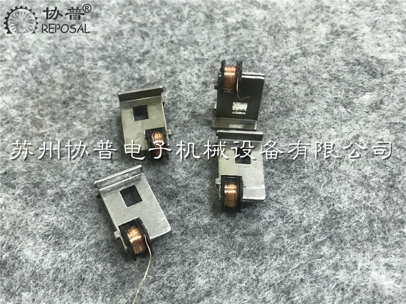
As shown in the figure, this miniature permanent magnet trip coil is widely used by ABB, EATON Muller compact circuit breaker, and has a compact structure. On a tiny metal structure bracket, a suction coil is wound that is closed to the metal structure. It seems simple, but its design technology is very strong. Therefore, it has been the industry enterprises in this kind of products to achieve the domestic industry barriers.
With the attitude of professional focus and the trust of advanced customers in the circuit breaker industry in Mongolia, REPOSAL® winding machine has gone all out to successfully reverse crack this technological process and help customers of REPOSAL® winding machine to make this product domestically smoothly.
Research and development background and characteristics of precision current transformer winding machine
Research and development background and characteristics of precision current transformer winding machine
The precision of coil in current transformer is very important, because it directly affects the accuracy of current measurement and the reliable operation of power system. The specific importance of coil accuracy is reflected in the following aspects.
Electrical energy metering: In a power system, accurate measurement of current is the key to calculating energy consumption. If the coil in the current transformer is not accurate, it will lead to an error in the measurement of electrical energy, which can lead to a miscalculation of energy costs, with possible financial implications for both the utility and the consumer.
Fault detection: The current transformer is used to monitor the current level to detect abnormal conditions in the power system, such as short circuit and overload. If the accuracy of the coil is not high, it may lead to false positives or neglect of potential faults, which affects the reliability of the power system.
Overcurrent protection: Current transformers play a key role in overcurrent protection devices, detecting overcurrent events and triggering circuit breakers or other protective devices. The accuracy of the coil directly affects whether the overcurrent can be accurately detected to ensure the safety of the power system.
Load management: The load management of a power system requires accurate measurement of current in order to make reasonable load distribution and adjustment. If the precision of the coil is not high, it may lead to unbalanced load distribution, affecting the efficiency and stability of the power system.
Automated control: In modern power systems, automated control systems rely on accurate current measurement data for real-time adjustment and control. The precision of the coil is critical to the response speed and performance of the system.
Waveform analysis: Current transformers are also used for power quality analysis, including harmonic analysis. The precision of the coil determines the accurate analysis of the current waveform, which helps to solve the power quality problem.