Design and verification of winding machine for precision voltage transformer
In power transmission and power supply systems such as power plants and substations, voltage transformers are an indispensable electrical appliance. The voltage transformer for measurement specifies the accuracy level of the voltage transformer according to the error generated when the voltage is changed. Voltage transformers of level 0. 2 and above are generally called precision voltage transformers, which are mainly used in the laboratory to expand the measurement limit with the standard meter for precise measurement of voltage, power and electrical energy; or as a standard to check low standards, Low-accuracy voltage transformer; it can also be used with standard meters to test the corresponding meters.
With the rapid development of science and technology and electronic application technology, the requirements for technical indicators such as the rated primary voltage and accuracy of voltage transformers are getting higher and higher, and the demand for various types of voltage transformers is increasing. In the past, voltage transformers were mostly manually wound with annular iron cores and thick enameled wires. The products were large and heavy. In the daily winding, processing and production process, the degree of mechanization was not high, the labor intensity of workers was high, and the production efficiency was low. It is necessary to improve the voltage transformer design process and develop a new type of mechanical equipment for winding the voltage transformer.
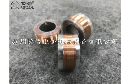
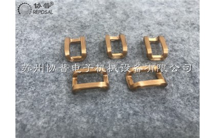
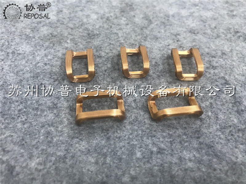
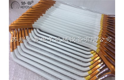
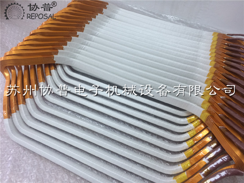
The structure of precision voltage transformer:
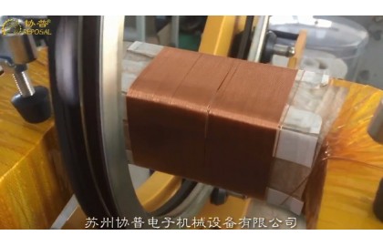
The precision voltage transformer is mainly composed of primary winding, secondary winding, iron core and insulating material. The primary winding is directly wound on the R-shaped ladder core, and the number of turns of the secondary winding varies with the change of the secondary voltage and the error level of the voltage transformer, ranging from tens of thousands of turns to hundreds of thousands of turns.
Design ideas of precision voltage transformer winding machine:
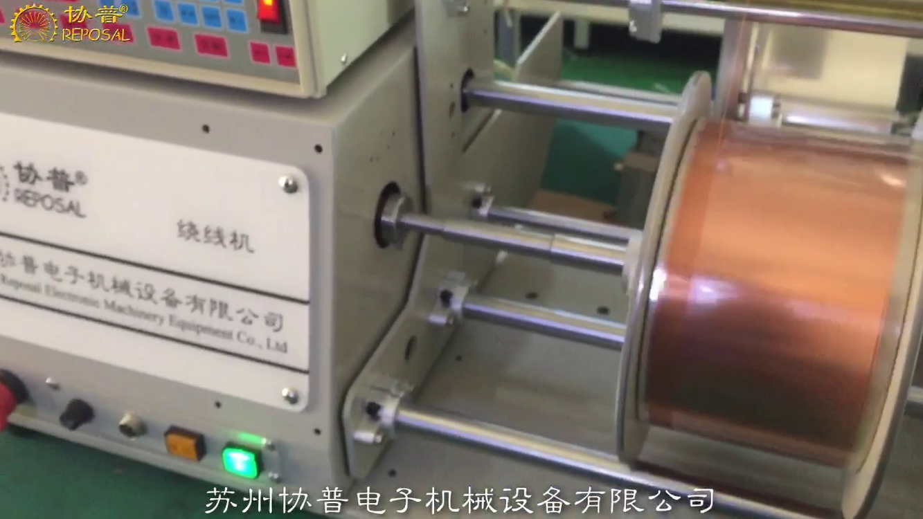
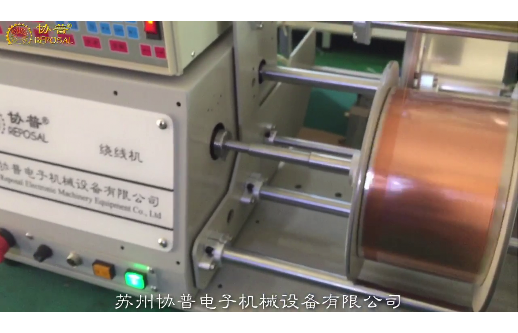
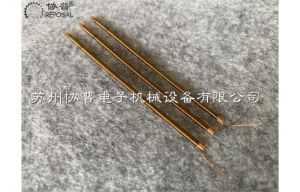
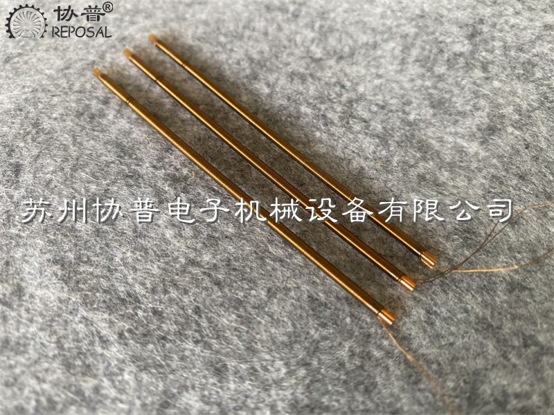
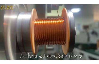
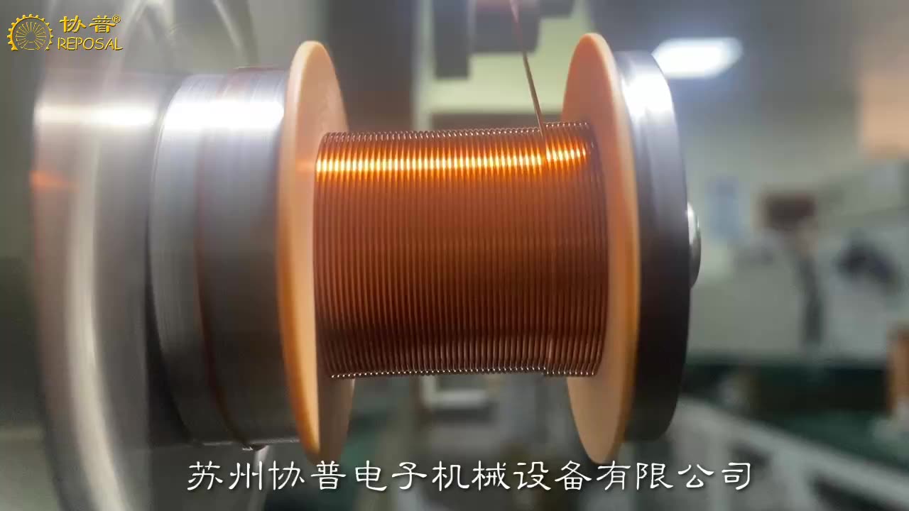
The secondary winding coil of precision voltage transformer has many turns, and the enameled wire used for winding is very thin, which cannot be completed manually. If mechanical equipment is used for winding, only the bobbin carrying the secondary winding can rotate, so that the enameled wire on the winding tool is wound on the bobbin fixed on the secondary winding in an orderly manner.
Since the power that the machine needs to transmit is low and the transmission efficiency requirements are not too high, the first-level transmission adopts belt transmission, and the flat belt transmits the movement and power of the motor to the main drive shaft.
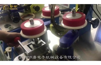
Text box: 7 Youqian friction transmission has simple structure, stable transmission, convenient transmission ratio adjustment, and slippage when overloaded to avoid damage to the device. Therefore, the secondary transmission adopts friction wheel transmission, that is, the transmission wheel fixed on the main drive shaft and the secondary winding bobbin rotating friction, and the movement and power are transmitted to the secondary winding bobbin.
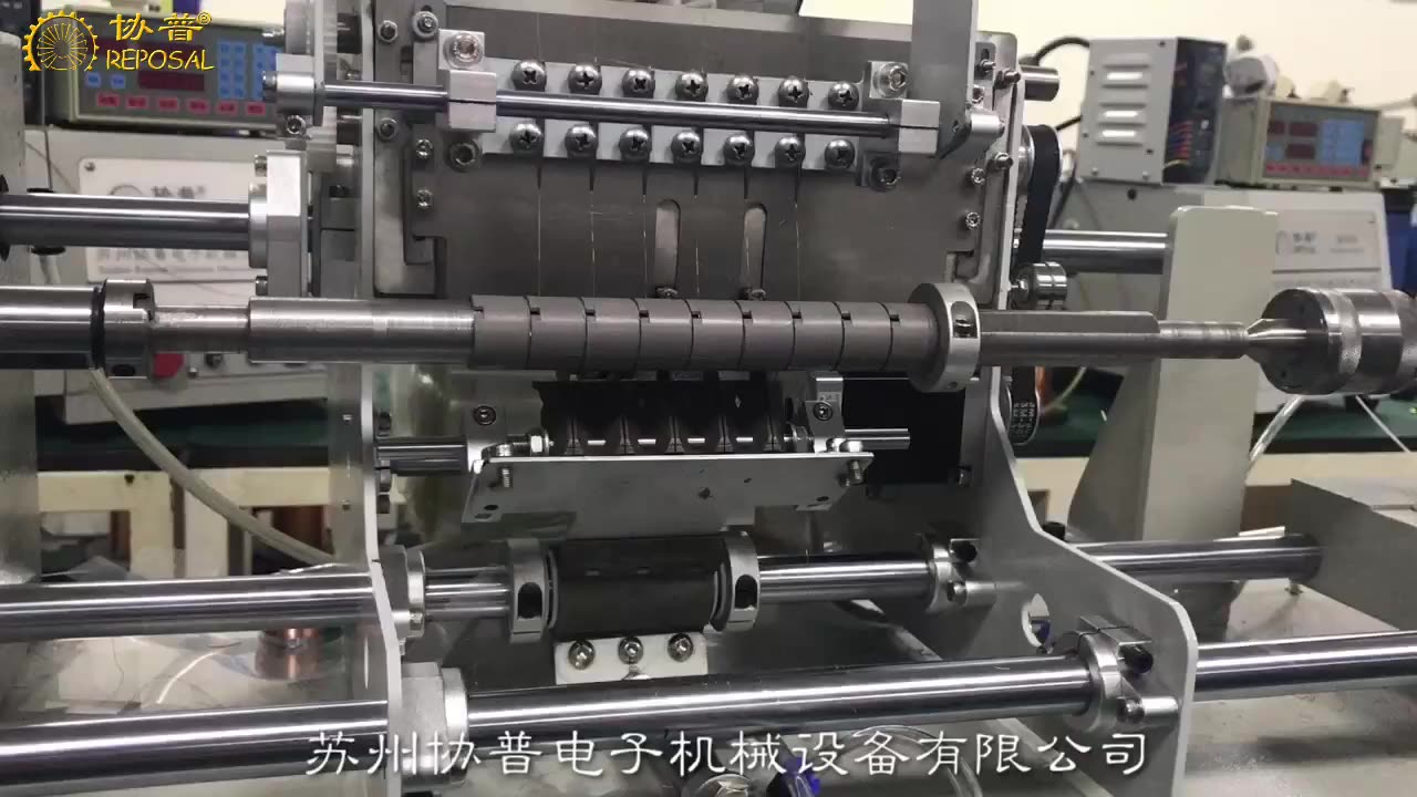
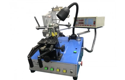
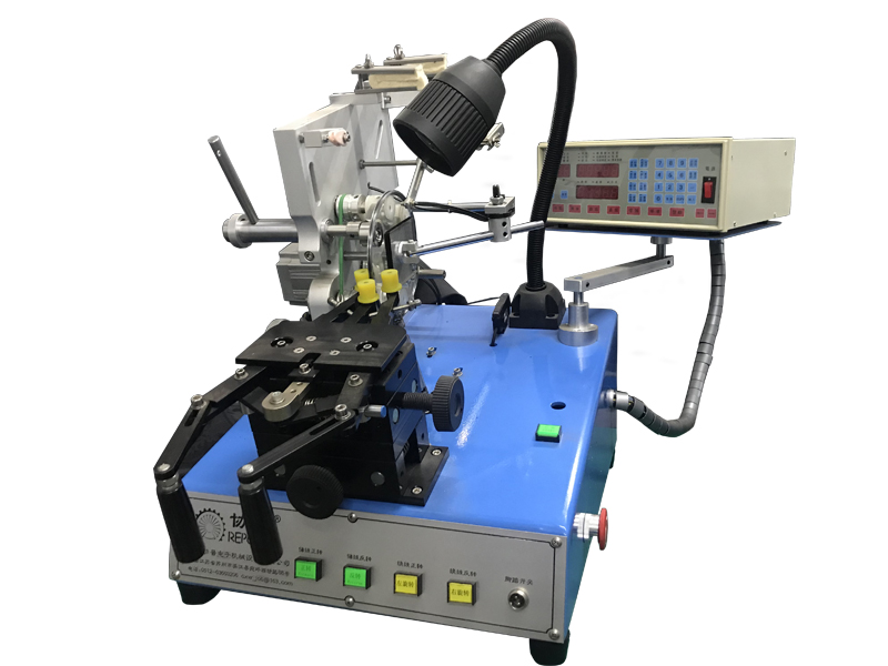
The main components of the winding machine
transmission
The power source of the voltage transformer winding machine is a DC brushless motor with a power of 0.6Kw and a speed of 6000 r/min.
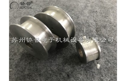
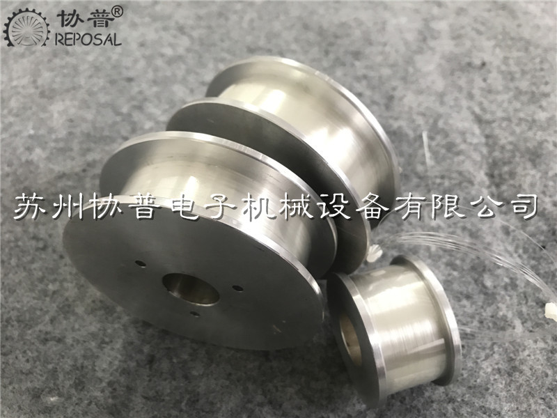
The secondary winding coil is wound with high-strength poly enameled round enameled wire, the diameter of the enameled wire is 0.08 mm-0.1 mm, and the strength limit is about 882 MPa. If the revolving speed of the secondary winding bobbin is too slow or too fast, it is easy to break the enameled wire. Through empirical analogy, related tests, working characteristics of the transmission and specific working conditions, as well as the counting speed of the counter and other comprehensive technical indicators, select the small pulley diameter d1 = 32 mm, the large pulley diameter d2 = 80 mm, and the main drive wheel diameter d3 =40 mm, the diameter d4 of the secondary winding bobbin of various voltage transformers is approximately 120 mm.
transmission shaft
This machine is low-power transmission, and the shaft speed is not high. The drive shaft is made of 45 steel, quenched and tempered, the hardness is 217 HBS ~ 235 HBS, and the strength limit is 650 MPa.
The axial force of this bearing is not large, so the bearing adopts 6201 deep groove ball bearing. The circumferential direction of the bearing adopts .H7/k6 interference fit, and the bearing cover is used for axial fixation. The main drive wheel on the drive shaft and the drive shaft adopt a H9/h9 clearance fit, and are fixed in the axial and circumferential directions with M5 set screws.
The high-strength polycool enameled round enameled wire on the winding tooling needs to be continuously wound on the secondary winding bobbin. When the number of coil turns reaches the design requirement, the bobbin carrying the secondary winding must stop rotating.
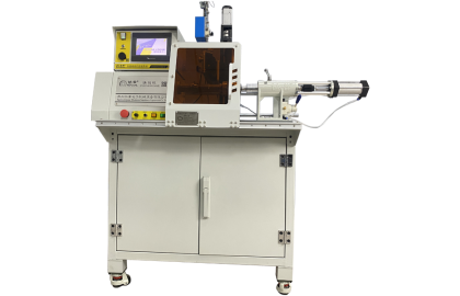
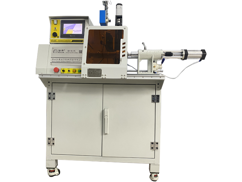
This machine uses REPOSAL® precision winding controller to count the number of coil turns. The resolution of the number of turns is 0.1 turns. When the number of turns of the coil reaches the set number, the relay contacts will change position, stop counting or continue counting, so as to achieve the purpose of accurately counting the number of coil turns.
Improvement direction:
With the continuous improvement of the technical performance and accuracy requirements of precision voltage transformers, the number of turns of the primary winding and the secondary winding will increase, and the quality of the winding must also be improved, so as to ensure the inter-turn and layer of the primary winding and the secondary winding. The quality of the insulating material between the windings and the windings. Therefore, under the premise of ensuring that the enameled wire is not damaged, the rotation speed of the wire frame can be appropriately increased, and the wiring mechanism can be improved; or the copper clad steel wire can be used in the design of the secondary winding to improve its strength, bending resistance, toughness and Torsion resistance and vibration resistance.
in conclusion:
When the voltage transformer winding machine is used to wind the secondary winding of the 35 kV precision voltage transformer, a 0.8 mm high-strength poly-enameled round enameled wire is used, the number of turns of the secondary winding is 110,000, and the winding time is 300 min. , The transmission efficiency is 91. 5%, which meets the expected design requirements. During the winding process of the machine, all parts of the machine are in good working condition, the counting is accurate, and the number of broken enameled wires is very few. With the action of the guide wheels, the enameled wires can basically be arranged in each grid of the wire frame in an orderly manner.
Related Post
REPOSAL® releases layer-wound high-voltage package full-automatic interlayer insulation winding machine
REPOSAL® releases layer-wound high-voltage package full-automatic interlayer insulation winding machine
Suzhou Xiepu Electronic Machinery Equipment Co., Ltd. successfully released the SP-D102M7 model of layer-wound high-voltage package automatic interlayer insulation winding machine-this model greatly improves the winding efficiency of layer-wound high-voltage package coils, and the coil is consistent Sex. The REPOSAL® winding machine reduces the winding cost of the layer-wound high-voltage package. In the new model, it has added a compact insulation belt automatic cutting mechanism, and high-quality solutions such as dynamic balance performance after multiple skeletons are wound.
Horseshoe hollow cup motor coil and winding machine
Horseshoe hollow cup motor coil and winding machine
In recent years, China has paid more and more attention to hollow cup motor and automatic winding technology, and has made good progress and breakthroughs in the research and development and manufacturing of winding machine equipment.
One of the key reasons for the impact on the performance of the motor is the rotor coil in the motor, the rotor in the hollow cup motor has no iron core, small inertia, excellent functionality and a wide range of applications. In addition, in the research and development of coil winding equipment, the saddle-shaped coil arrangement is regular, and the utilization efficiency of magnets is high.
Compared with the old traditional motor with an iron core, the energy conversion efficiency is significantly higher than the latter, and the reaction speed will be much faster, and the hollow cup motor has high efficiency, fast response speed and stable performance. Because the hollow cup motor has no lag, additional electromagnetic interference is low, very high motor speed can be achieved, and the speed setting is sensitive at high speed, so it has relatively stable and stable performance. In addition, the energy density of the hollow cup motor is much greater than that of other motors, and the weight will be much less than that of an iron core motor with the same power.
Now according to the forming method of the coil, in the hollow cup motor coil, its production technology can be roughly divided into two process routes: winding production technology and one molding production technology.
Compared with the two methods, the first winding production technology is more complex, and the efficiency of winding the coil is relatively low. In order to improve the winding efficiency of coil production, the winding machine can be added to the production process of one molding. According to the hollow cup coil shape and winding method, the common hollow cup winding method can be divided into three kinds of parallel straight winding, saddle winding and oblique winding. The first parallel straight winding is generally used for hollow cup motor winding with relatively few turns. The last two are the two coil winding processes commonly used by the relatively advanced hollow cup motor manufacturers abroad.
REPOSAL® machine for radiofrequency ablation catheter
The precise winding process ensures the efficient transfer of energy, thereby improving the efficiency and consistency of ablation. The uniformity of the precision wound coil affects the temperature distribution of the ablation area, avoiding local overheating or heat deficiency, which is essential to ensure the ablation effect and reduce complications. The stability of the winding process ensures the reliability of the operation. The high-quality winding process withstands stretching and bending during surgical operations, reducing the risk of breakage or functional failure. High-quality winding processes have a longer service life and are able to maintain stable performance through multiple operations, thereby reducing medical costs and improving resource efficiency. The quality of the winding process also affects the precise control of the ablation process. The high-precision winding process helps physicians to more precisely control the size and shape of the ablation area to achieve optimal treatment results.
Moreover, the RFA catheter winder is designed with operational safety in mind, reducing potential risks during operation and protecting operators and products from damage. It can adapt to different types of radiofrequency ablation catheter production requirements, and has good flexibility and scalability. The structure and design of special winding machines are often more simplified and easier to maintain and maintain, thus reducing long-term operating costs.
The advantages of radiofrequency ablation catheter winding machine are mainly reflected in professional design, high efficiency production, precise control, quality stability, easy operation, material saving, safety, strong adaptability, low maintenance cost and technological innovation. These advantages make the radiofrequency ablation catheter winding machine an indispensable key equipment in the production process of radiofrequency ablation catheter.
Study on the control of the speed curve of the coiling machine for precision coiling machine
Your factory is using a traditional winding machine, your wire machine structure is reasonable, high mechanical accuracy, the motor is also used a big brand of motor, but in the winding of precision coils, there will be a high defect rate, you carefully analyze before improving various factors - equipment structure, processing accuracy, tooling accuracy, skeleton accuracy, enamel wire quality, tension control, etc. But it still doesn't solve the problem. But to tell you that it's not just a hardware problem, but an algorithm problem, may surprise you. Because in your opinion, every time the spool is transferred, the spool has a corresponding response, but in fact, you may not have considered that in the winding process of the precision coil, the wire guide pin is connected at both ends of the coil, and the sudden change in speed may cause the coil to cross the line and be raised. These defects can degrade the performance of the coil.
To solve this problem, we propose an acceleration and deceleration method based on 5-segment S-curve. The algorithm uses linear acceleration or deceleration at the end and end of the line motion control to help reduce coil defects. We first verify the feasibility of the algorithm by using ADAMS software. The software simulates the motion of the precision winding coil and obtains the velocity curve and displacement curve during the motion. Later, the experimental results show that the method of adopting S-curve in the alignment speed control can reduce the coil defect by up to 50%. This shows that the 5-section S-curve motion control algorithm is a promising method to improve the precision and efficiency of the winding process of electric precision coils. By using this algorithm, coil manufacturers can reduce the risk of coil defects and improve coil performance.
Winding machine is a special production equipment for precision winding coils. They can be divided into stator winding machine, flying fork winding machine, ring winding machine and flat winding machine according to the working mode and object. Different types of equipment are suitable for the production of different objects. For example, the stator winding machine is mainly used to produce motor stator coils, while the parallel winding machine is used to produce electromagnetic switching coils.
Ordinary algorithm of parallel winding machine in the production of precision winding coil products, although our mechanical structure, parts processing accuracy has been done very well, but often there is a problem of low wiring accuracy. In the process of winding a line coil, there are two main movements, one is the rotating movement of the skeleton, which is called winding movement, and the other is the translation movement of the guide needle, which is called wiring movement, and wiring transport is matched with winding movement. After years of technical accumulation, we analyze that the leading role in the alignment accuracy is the alignment movement of the guide needle. Therefore, if you want to improve the alignment accuracy of the coil, you need to optimize the alignment movement of the guide pin.
In fact, we have always believed that the winding machine is equivalent to the lathe in the electrical industry, its importance is self-evident, so for its accuracy, there have been many experts and scholars to study this.
Some people studied the mathematical model of precise alignment based on axial pressure compensation around the axis in the process of alignment. The axial pressure was used to improve the alignment regularity of the coil, and the mathematical model was established according to the analysis of the end point of the coil alignment, which improved the alignment accuracy of the coil.
Some people use the 5-section S-curve control algorithm and the 7-section S-curve control algorithm respectively in the research. In motion control, the 7-section S-curve is more complicated than the 5-section S-curve control. This method has achieved more results in the field of CNC machining, but it is not mature in the field of winding machine.
The tension instability caused by the friction between the enamelled wire and the conductor nozzle during coil winding has been studied, which leads to the uneven wiring of the coil and the breakage of the enamelled wire.
Some people have studied the low efficiency of the winding machine in the traditional winding control because of the inertia error in the process of the winding machine. Instead, the servo motion wiring and the inertia error supplement are used to improve the control efficiency of the winding machine.
PLC control is commonly used in the winding machine wiring control system, through PLC control servo motor can realize the winding machine wiring control, both PLC control stability and high precision servo motor advantages. However, there is a sudden impact of guide pin speed in the coil alignment of parallel winding machine, so it is necessary to further optimize the change of guide pin running speed to improve product quality and the smoothness of wire alignment speed. The S-curve algorithm is a kind of smooth transition of speed in the process of motion, which is often used in machining to solve the problem of breaking the tool caused by speed impact and improve the precision of machining products. In the winding machine, the speed of the guide needle can be changed into an arc smooth transition by controlling the movement track of the guide needle, improving the alignment accuracy and product quality.
To sum up, an algorithm based on 5-segment S-curve motion control is proposed to solve the problem of velocity shock in the process of coil alignment by analyzing the law of coil alignment. ADAMS software is used to simulate the trajectory of the guide pin to verify the feasibility of the algorithm. And the application of the example proves that the 5-section S-shaped curve can effectively solve the phenomenon of crossing and protruding in the process of winding, and improve the precision of winding.
Coil wiring principle
The winding method is flat winding, that is, the enameled wire moves synchronously with the guide pin and always keeps perpendicular to the skeleton during winding. The frame is driven by the winding motor with the guide needle movement, the enameled wire is wound on the skeleton, in which the guide needle is located in the wiring arrangement mechanism and the winding mechanism are two independent mechanisms. The winding mechanism is divided into three stages according to the motion process of the guide pin, namely acceleration and deceleration stage, uniform speed stage and end point return stage. The acceleration and deceleration stage can be divided into two parts: acceleration stage and deceleration stage. In the early stage of the alignment movement, the guide pin speed from zero to uniform speed belongs to the acceleration stage. At the end of the alignment movement, the process of decelerating until the speed reaches zero is a deceleration stage. The middle constant velocity stage is the constant velocity motion stage of the guiding needle. The terminal reentry stage is a process in which the guide needle accelerates backward again after slowing down and stopping. Here we explain:
Acceleration and deceleration stage
In order to arrange the lines evenly, the two movements of guide pin movement and skeleton rotation should meet certain coordination relations during acceleration and deceleration stage. The time for the guide needle to move one diametral width distance must be equal to the time for the skeleton to rotate once, that is, the guide needle to move just one diametral distance when the skeleton rotates once.
Fiber Optic Gyro Winding Machine-REPOSAL® Winding Machine Official Website
Compared with mechanical gyroscopes, fiber optic gyroscopes have no moving parts, impact resistance, high sensitivity, and long life. Therefore, fiber optic gyroscopes are widely used in high-precision and high-speed positioning scenarios and will gradually replace electromechanical gyroscopes.
The basic components of the fiber optic gyroscope are the optical path and the circuit, and the fiber is the core component of the gyroscope. The fiber winding machine for preparing high-precision fiber coils has also become the key point of the gyroscope.
However, due to the blockade of its related technologies, the fiber optic gyro winding machine has always been a key technology insurmountable. REPOSAL® Electronic Machinery Co., Ltd. actively develops fiber optic gyro winding machines in response to market demand.
Through continuous research and improvement, we automate the winding process of the fiber optic gyroscope, and compare and analyze the winding methods of various fiber coils. We have obtained that the tension control and the accuracy of the winding during the fiber winding process affect the structure of the wound fiber coil. The key factor.
By optimizing the aforementioned tension control factors and winding accuracy algorithm, the effective and stable control of reasonable tension, the effective and reliable high-precision winding control, the memory of all process parameters, and the convenience of control, a new generation of optical fiber winding machine was developed and put into production .
With the practical application of research and development results, we will continue to improve and produce high-reliability and high-efficiency fiber optic gyro winding machines.
Process requirements of traction motor winding machine
Traction motors are mainly used for railway mainline electric locomotives, industrial and mining electric locomotives, electric drive diesel locomotives and various electric vehicles (such as battery cars, urban trams, subway electric vehicles).
The constraints of the coil during the winding process of the winding machine mainly come from two aspects: design requirements and craftsmanship. The specific manifestations are:
The structural design of coils and windings must not only meet the requirements of electrical performance and temperature rise limit, but also the applicability of existing winding machines, the economical and reasonable use of electromagnetic wires and insulating materials, simple structure and convenient manufacturing, that is, it should have Good manufacturability. In order to achieve better manufacturability and reliability, there are some control points that must be considered in the early stage. For this type of problem, REPOSAL®winding machine shares some content with you.
Analysis of winding tension of loop winding machine
Analysis of winding tension of loop winding machine
Toroidal winding machine-Toroidal coil winding machine-Enameled wire is wound radially on the closed toroidal structure (for details, please refer to the toroidal winding machine tutorial): With the rapid development of the domestic power industry, the demand for current transformer coils Increasingly, the development of current transformer coil winding equipment is imminent. In order to meet the needs of the market, we have developed a current transformer toroidal coil winding machine based on imported equipment. During the design and testing process, we found that, The key to the design of toroidal winding machine is the control of winding tension.
This automatic winding machine is composed of a frame, a pay-off mechanism, a winding head, a tape head, a clamping device, and a control system.
loop winding machine, automatic winding machine,
1, the working principle of toroidal winding machine
Firstly, the wires are evenly wound on the wire storage ring, and then the wires wound on the wire storage ring are wound on the skeleton by a shuttle. The skeleton is driven by the servo motor to rotate, so that the wires are evenly arranged on the skeleton when the wire is wound to a certain amount , And then wind the tape on the frame through the wire storage ring, and then wind it.
2, analysis of winding tension
Through our continuous practice, we have discovered that during the entire winding process, using appropriate force to wind the wire tightly on the skeleton is the key to the quality of the winding. Therefore, we will focus on the factors that affect the winding tension.
1. The grinding moment of the rotating part of the thread bobbin
2. The moment of inertia caused by the acceleration of the thread bobbin part (including the wire wrapped in the bobbin).
The main part of the frictional torque is generated by the tension mechanism, which prevents the wire shuttle from moving and tightens the wire to generate winding tension.
Due to the influence of the winding ring surface and its deviation from the center position in the winding gear, even if the winding is at a constant speed, the movement speed of the thread shuttle is small and uniform, which generates the moment of inertia caused by acceleration, which affects the winding tension.
The movement speed of the thread shuttle can be regarded as composed of two speeds: one is the speed Vo equal to the speed of the pulley on the winding gear, and the other is the speed at which the thread shuttle releases the amount of wire. The former is a constant, and the latter is calculated as follows ( see picture 1)
loop winding machine winding tension analysis 1
So in order to reduce the acceleration of the thread bobbin, it is required:
1. The frame profile H should be small, and the profile should be as close as possible to the center of the winding gear, that is, the value of 1 should be small.
2. The thread hook flat diameter R should be as small as possible.
3. The winding speed ω cannot be too high (this is in conflict with improving production efficiency).
The approximate curve of the speed Vx and acceleration а of the mountain thread shuttle is obtained by the graphical method, and the description is as follows (see Figure 2 and Figure 3):
loop winding machine winding tension analysis 2
1. When the small pulley on the winding gear is at the 0° position, the speed of the thread shuttle is equal to the speed of the small pulley V0, when the speed of the thread shuttle gradually increases from 0-60°, there is a positive acceleration at this time. =600-180`) when the thread shuttle moves at a constant speed, the speed is Vm>Vo. When а=180°~263°, the speed of the thread shuttle gradually decreases. At this time, there is a negative acceleration a = 263°. The speed of the thread shuttle is equal to the pulley speed V. When а=263°~345°, the speed of the thread shuttle continues to decrease. Small, that is, it is lower than V and has a negative acceleration. When а=345°, the speed of the thread shuttle is the minimum Vo, when а=345°~360°, the speed of the thread shuttle increases gradually and there is a positive acceleration.
2. When the winding gear rotates at a constant speed, the speed of the thread shuttle will be zero if it is small, so the friction tension mechanism always acts as a brake to keep the wire tensioned.
3. If Vp is the average linear velocity of the thread bobbin; Vo is the linear velocity of the pulley on the winding gear; L is the perimeter of the wire of the potentiometer, then
4. When the winding speed ω is not large: the wire bobbin diameter R is small, and the potentiometer profile size H is also small. When the profile is as close as possible to the center of the winding gear, the acceleration change is small and large, and the inertia caused by the acceleration The torque is much smaller
Debugging method and video of winding machine
Debugging method and video of winding machine
1. Preparation work before turning on the winding machine.
As a kind of precision equipment, in order to keep the winding machine with good working accuracy for a long time, at the same time, the winding machine is a equipment with rotation as the main movement feature. In order to ensure the safety of the process, we need to carefully check the winding machine before the machine. Whether there is debris on the workbench, whether the screws on the winding machine are loose, whether the power switch is properly connected, whether the specification of the enameled wire meets the requirements, confirm that there are no problems with the above problems before starting the machine.
2. Parameter setting of precision winding machine
Press the reset button on the winding machine controller, or press the reset button on the front of the winding machine, the winding machine will automatically reset, at this time, if you need to set the winding machine parameters according to the production schedule. Then press the "step sequence setting" "input" button on the controller of the winding machine in turn, and then press the input key, the cursor will jump backwards in turn at the prompt light on the screen, "starting point", "width" ", "wire diameter", "number of laps", "start winding slow withdrawal", "stop slow", "high speed", "low speed", "wire direction", "winding direction" and other parameters, and finally press "confirm" "Button to confirm, and press the "reset" button to save the data and reset automatically, the parameter setting is completed.
After entering the setting interface according to the step-by-step setting input, pay attention, press the input again to scroll back, and press the-number to scroll forward. When you turn to each parameter, you can enter the corresponding number according to the actual process requirements. For this parameter, you can modify the parameter by typing in the number, or you can adjust the position in real time through the right or right key at the bottom right of the winding machine controller. At the same time, the number in the parameter box will change accordingly in real time.
High-speed transformer winding machine
High-speed transformer winding machine
Gear type ring coil wrapping tape machine
Gear type ring coil wrapping tape machine
Compared with the belt-type loop coil tape belt machine, the gear-type loop coil tape belt machine has a larger processing range and more storage capacity. Our company's gear-type loop coil belt tape machine can be coated with polyester film and polymer Imide, cloth tape, glass fiber tape, etc.
We now open the clamping seat of the gear-type ring coil tape belt machine, the storage ring opens, and then put the product on, the storage ring buckles, the clamping seat merges, and then pay attention to the insulating tape must pass through the middle of the scissors, etc. Cut it off with scissors at once, and then go in from any bearing above the storage ring from the outside to fix the tape head behind the storage ring. The first few laps are slow because they are in storage. Ok, the product is finished, now we take it off, and then close the storage ring, the clamping seat is restored.
REPOSAL Winding Machine General Operation Manual
 1. Safety Instructions (Must Be Strictly Followed)
1.1 Personnel Qualification Requirements
- Operators must complete systematic pre-job training, be familiar with the equipment structure, functions and operating procedures, and can only take independent posts after passing the assessment.
- Unauthorized personnel and minors are strictly prohibited from operating the equipment.
- It is strictly prohibited to operate the equipment under the influence of alcohol, excessive fatigue or drugs.
- Operators must wear standard work clothes, safety goggles and anti-smash safety shoes during operation. Do not wear gloves, ties, necklaces, loose cuffs or other items that may be caught by rotating components.
1.2 Operating Environment and Equipment Inspection
Environmental Requirements
Installation Requirements
- The equipment foundation must be stable and firm (levelness ≤0.2mm/m).
- A maintenance channel of ≥80cm shall be reserved around the equipment.
- Fire-fighting equipment shall be equipped nearby, and stacking of sundries is prohibited.