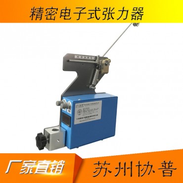

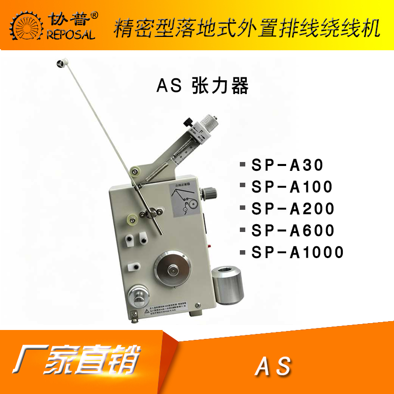
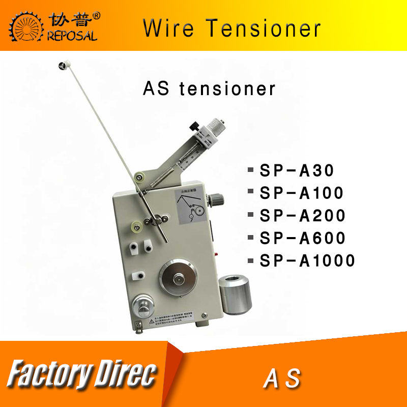
Electronic tensioner-as
- Brand: 协普/REPOSAL
- Product Code: Electronic-tensioner-AS
- Availability: In Stock
- Ex Tax: login to see prices
Product specification and model:
| TCL Tensioner | Specification | Tension Range | Wire Size | Dimension | |
| AS Series Tensioner | SP-A30 | 3--30 | 0.03-0.06 | 15*10*26 | |
| SP-A100 | 10-100 | 0.04-0.14 | 15*10*26 | ||
| SP-A200 | 20-200 | 0.06-0.16 | 15*10*26 | ||
| SP-A600 | 80-600 | 0.1-0.35 | 15*10*26 | ||
| SP-A1000 | 100-1000 | 0.12-0.48 | 15*10*26 |
Notes:
1. Do not touch transmission and rotating parts or block the tension lever when using the tensioner.
2. Prevent the tensioner from falling and avoid damage caused by strong impacts.
3. Adjust the felt pressure (not too high) and tension spring strength appropriately during use to ensure normal operation of the controller.
4. When setting the current value from high to low, turn the tension wheel while reducing the value to eliminate tension pulsation; otherwise, the winding effect will be affected.
5. When enameled wire jams the tension wheel, loosen the fixing screws to take out the tension wheel and remove debris.
6. Pass the enameled wire through the ceramic ring and route it sequentially through relevant parts of the tensioner following the dashed path in the outline drawing.
7. Adjust and replace the felt regularly according to service conditions to ensure the controller works properly.
Product Operation:
1. Install the tension lever and tension spring. Select appropriate tension lever and tension spring (choose the proper tension spring according to the wire diameter range and tension range of the selected tensioner; tension springs with greater tension are used for wires requiring higher tension / thicker wires) and assemble them as shown in the diagram. Notes during product assembly: The inserted depth of the tail of the tension lever must exceed the elastic rubber stopper at the lower end, yet it should not be too close to the tension wheel. Tighten the screws after adjusting the position.
2. Adjust the counter tension. Adjust the counter tension by changing the position of the tension spring fixing block and the tension spring on the block. After adjustment, the tension lever must closely press against the lower elastic rubber stopper. Tighten the fixing screws once the position is set.
3. Set output tension. After power-on, the tensioner displays the current value of "Setting 1" by default. Adjust the output tension magnitude by turning the knob "Setting 1" to change the current value. Refer to the knob and button instructions for detailed adjustment methods.
4. Tension control. The wire passes through the tensioner, which feeds wire passively. Based on the hysteresis principle, it generates a certain torque by controlling the input excitation current to achieve stable tension control (the excitation current has a good linear relationship with the torque value).
.png)
Knob and Button Instructions:
This tensioner can set two separate adjustable tensions, which are regulated by Knob "Setting 1" and Knob "Setting 2" respectively. The "Setting 2 Display / Adjustment" button assists with adjustment. Detailed description:
1. Knob "Setting 1": Rotating this knob in any state will change the current value of "Setting 1".
2. Knob "Setting 2": Rotating this knob in any state will change the current value of "Setting 2".
3. Button "Setting 2 Display / Adjustment": When the display shows the current value of "Setting 1", pressing and holding this button will make the display show the current value of "Setting 2" (to assist "Setting 2" adjustment, not for switching). Note: The higher the current value, the greater the tension, and vice versa. The current values of "Setting 1" and "Setting 2" can be switched by connecting an external signal for control.
Warranty Statement:
1. The tensioner is covered by a three-month warranty starting from the date of purchase.
2. For repairs requested after the warranty period expires, a service fee will be charged.
3. Even within the free warranty period, the user shall bear the repair costs under the following circumstances:
a). Replacement of wearing parts: wool rings, guide ceramic parts, thread passing wheels, tension levers;
b). Damage caused by improper use or force majeure;
c). Unauthorized disassembly without permission from our company;
d). Damage resulting from use of an unsuitable model or operation beyond the specified scope;
e). Other situations of similar types mentioned above.