Structure-of-high-frequency-transformer-winding-machine
Structure-of-high-frequency-transformer-winding-machine
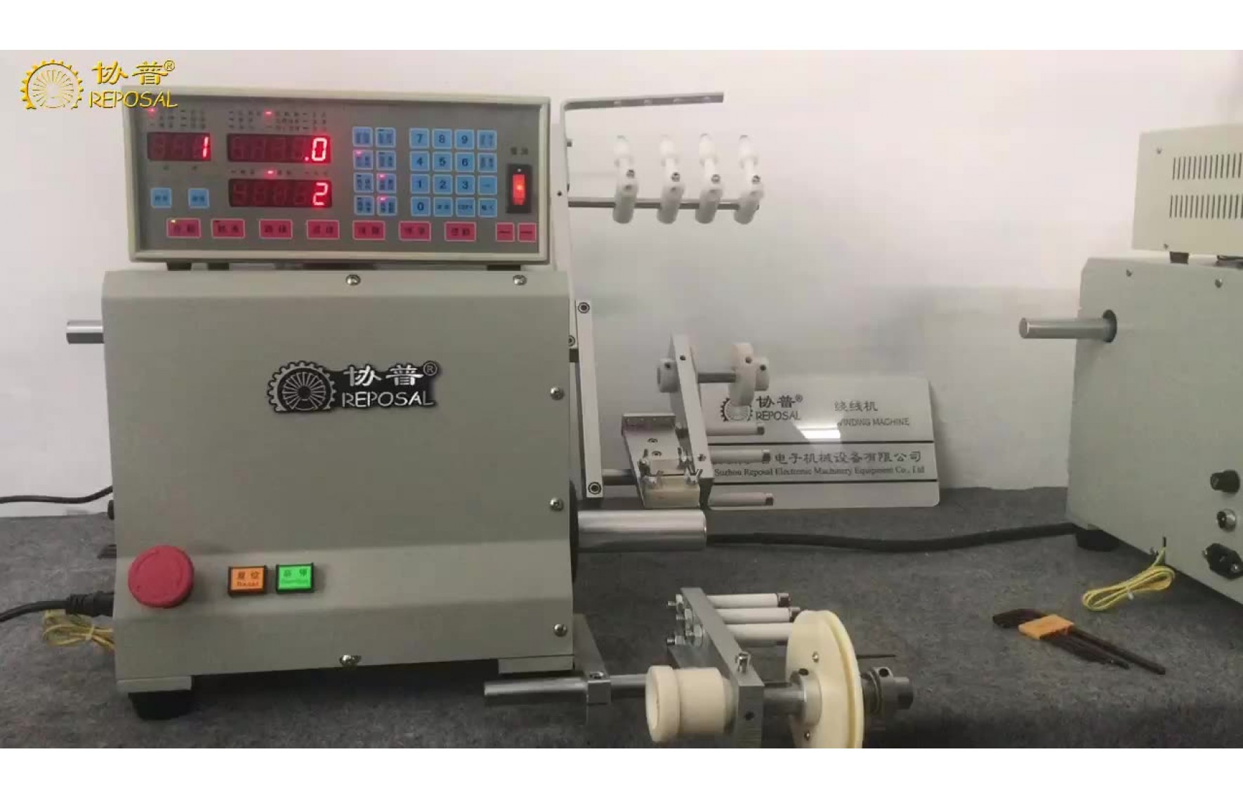
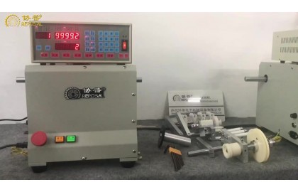
This video explains the structure of the high-frequency transformer winding machine. The general simple winding machine structure is roughly divided into several parts. The first part is the winding part, which is the winding shaft, and the second part is the winding part, which is the winding shaft. The mechanism that makes the enameled wire reciprocate while rotating. The third part is the wire passing mechanism, that is, the part between the enameled wire from the original cylinder to the tension mechanism. This part is usually composed of some bracket parts, and the fourth part is the tension part. To provide unequal tension required for winding the enameled wire on the coil, the fifth part is the winding head part, that is, the winding machine has passed the tensioner and obtained tension, and the part of the mechanism that will be wound on the coil. The high-frequency transformer is because of its design. Targeted, compared with the general simple winding machine, because its windings are more, the structure is compact, and the product requirements are not high, so there is no tensioner part, but because high-frequency transformers mostly require wall tape and insulating tape, So compared with the general simple winding machine, these two parts are more.
Let's briefly introduce the structure of this transformer winding machine.
Why did he name this winding machine the transformer winding machine?
Because it can support multiple enameled wires of different specifications at the same time.
Every enameled wire is from this position to this position.
Then pass the ceramic circle.
Then go through wool felt.
Then there are different holes from small to large.
Here are 4 such ceramic circles.
Like this.
In this way, he can clamp it all at once.
The skeleton of the transformer is installed in this position.
It can be wound with 4 enameled wires of different specifications at a time.
Enameled wires of different specifications.
This position is used to put the retaining wall tape on both sides of the high-frequency transformer skeleton.
This position is used to place the insulating tape of the high-frequency transformer.
So this machine is suitable for winding high frequency transformers.
Related Post

Structure-of-high-frequency-transformer-winding-machine
This video explains the structure of the high-frequency transformer winding machine. The general simple winding machine structure is roughly divided into several parts. The first part is the winding part, which is the winding shaft, and the second part is the winding part, which is the winding shaft. The mechanism that makes the enameled wire reciprocate while rotating. The third part is the wire passing mechanism, that is, the part between the enameled wire from the original cylinder to the tension mechanism. This part is usually composed of some bracket parts, and the fourth part is the tension part. To provide unequal tension required for winding the enameled wire on the coil, the fifth part is the winding head part, that is, the winding machine has passed the tensioner and obtained tension, and the part of the mechanism that will be wound on the coil. The high-frequency transformer is because of its design. Targeted, compared with the general simple winding machine, because its windings are more, the structure is compact, and the product requirements are not high, so there is no tensioner part, but because high-frequency transformers mostly require wall tape and insulating tape, So compared with the general simple winding machine, these two parts are more.
Let's briefly introduce the structure of this transformer winding machine.
Why did he name this winding machine the transformer winding machine?
Because it can support multiple enameled wires of different specifications at the same time.
Every enameled wire is from this position to this position.
Then pass the ceramic circle.
Then go through wool felt.
Then there are different holes from small to large.
Here are 4 such ceramic circles.
Like this.
In this way, he can clamp it all at once.
The skeleton of the transformer is installed in this position.
It can be wound with 4 enameled wires of different specifications at a time.
Enameled wires of different specifications.
This position is used to put the retaining wall tape on both sides of the high-frequency transformer skeleton.
This position is used to place the insulating tape of the high-frequency transformer.
So this machine is suitable for winding high frequency transformers.
Continuous-execution-of-multiple-programs-of-the-winding-machine
The company's CNC winding machine allows storage of 1000 sets of process data, and supports continuous execution of multiple sets of process data. The number of consecutive execution groups can be set from 2 to 1000 groups. This function is more complicated for the process and requires multiple external The intervention product provides great convenience and flexibility. The following winding machine operation video introduces the specific setting method.
Below we explain the two procedures of the Xiepu winding machine,
Or continuous automatic execution between multiple programs,
In other words, after bypassing the first program,
Then the second program is executed automatically,
No need for you to press the start button in the middle,
Let's demonstrate,
How the settings are set,
First "step sequence setting" "input"
In the second program,
We put "autostart"
Is now open,
Then the "autostart" of the first program we have to close it,
Because if this is the "autostart" of the first program,
It will become an infinite loop,
Turn it off now,
Then press "Enter" and press "Reset"
All right,
Then we pay attention to the "" light in the lower left corner to turn on,
Then we press start.
Storage-and-recall-of-winding-machine-process-parameters
The company's CNC winding machine supports the storage of 1000 sets of winding process data. After you complete the winding process data of a coil, it will be automatically saved. When you debug the next product, you only need to start the setting from the next program number The parameters are enough. When you need to produce the original product, you can also call it very conveniently. The video below illustrates the storage and recall of the company's winding machine process data.
Let's introduce the process program of REPOSAL automatic winding machine.
Store and recall.
It can be stored in Xiepu's automatic winding machine controller.
1000 different process procedures.
How do we switch.
Press the starting step.
Press 1 and press enter.
Then press the end order.
Press 1 to enter and press to reset.
Then we set the order by part and press the input.
We will find that we continue to press enter.
Press the words after entering.
It will be set within the scope of Procedure 1.
Starting point means to start from where.
We can specify by this arrow.
We can also enter numbers directly.
For example, this is 36.5.
We can enter 37.
This is the starting point.
Then we can specify the width for him.
The width we are talking about is how big the line is.
Winding back and forth within a range.
Then we can set his enameled wire diameter.
For example, the diameter of the enameled wire is 0.4 mm.
Setting-of-technological-parameters-of-winding-machine
The company's CNC winding machine controller has been continuously improved, with complete functions and stable performance. It can accurately set the main parameters such as starting point, wire diameter, width, high speed, low speed, etc., and also include such as start slow speed, stop Auxiliary parameters such as slow speed, stop at both ends, these commonly used parameters are designed in the user parameter setting area. The following video explains the parameter setting process of our company's CNC winding machine in more detail:
Now we introduce the setting of process parameters of Xiepu winding machine.
The controller of Xiepu winding machine is divided into these major functions.
This part is called the digital parameter area.
It represents the current state of the machine.
For example, the red light here corresponds to the standby state.
It means that this machine is in standby state.
The following states are running, slowing, positioning, speeding.
This is a status area to monitor the current status of the machine.
This is a numeric parameter area.
The digital parameters need to be some numbers that we need to set.
at this place.
This is a switch parameter.
For example, when the cable direction starts.
Whether from left to right or right to left.
This is the cable direction.
There is also the winding direction.
For example, when we are standing on the right side of the machine.
See if the spool is rotating clockwise or counterclockwise.
Then choose the direction.
Then there are some special functions.
For example, parking at both ends, automatic stopping, automatic homing, etc.
These functions may need to be turned on.
This is a parameter of the nature of the switch.
So this is a switch parameter area.
This part is an editing area.
It is our numbers and clear, copy, confirm, etc.
This is in the editing area.
Then this is an interrupt area outside the interrupt area.
For example, we need to specify the automatic mode.
Or retreat, jump, stop, start.
Assembly-of-high-frequency-transformer-winding-machine
Assembly-of-high-frequency-transformer-winding-machine