Winding machine selection
In the narrow sense, the winding machine mainly refers to the winding machine of various enamelled wire coils, these coils may be transformers, relays, inductors, current transformers, various sensors, these coils can be seen everywhere in our lives, the common feature is to use enamelled wire winding, the difference is according to the design requirements, and the cost and efficiency requirements of industrial products, Its winding process is not corresponding, so derived from a variety of different winding machine, we show on the official website is only a part of the conventional winding machine, and some are customized, or special industries are not displayed, if you need to know, you can contact us.
Coils can be seen everywhere in our lives, such as the electric meter in the home, there are metering induction coils, trip coils in the circuit breaker, transformer coils in the community, various motor coils in industrial automation, various sensor coils, starting coils on the car, ignition coils, power motor coils on the bullet train, etc., it is no exaggeration to say that we live in a world of coils. There are so many coils, and the corresponding winding machines are different, so the winding machine is as important to the electrical world as the lathe is to the mechanical world.
There are so many types of winding machines, if you are not familiar with them, those selections have become a big problem, we now make a simple introduction from several aspects.
One is the winding method, which is generally divided into parallel winding machine, toroidal winding machine, and flying fork winding machine.
Parallel winding machine: most of the cylindrical coil and rectangular coil, enameled wire and enameled wire are approximately parallel, the main structure of this winding machine is a motor control winding shaft, the other motor control axis, the two axes with interpolation relationship to move, rotate a certain Angle around the axis, the axis is moved a corresponding distance.
The parallel winding machine has two different layouts according to the direction of the shaft, one is the right side of the shaft, and the majority of the single-axis machine uses this direction, because it is conducive to right-handed operation during the winding process, and more importantly, the operator can easily observe the arrangement of the winding, which is especially important for high-demand coils. There is also a positive out of the shaft, it is because of the need for high frequency loading and unloading of the coil skeleton, the advantage of the positive out of the shaft is that the skeleton is pulled in the direction of the operator's chest, and the skeleton is pushed forward by the operator, so it is more labor-saving, but its disadvantage is that due to the concentration effect of the eyes, it is difficult to observe the winding quality of the coil in real time.
The high frequency loading and unloading of the front shaft is mainly determined by the number of turns of the coil, such as the process speed of a winding machine is 3000RPM, which can be wound 50 turns per second, if the number of turns of a coil is only 100 turns, then two seconds after the start can be wound to complete, such as the speaker voice coil is a typical coil, the machine dynamic rate of this coil is relatively low. The loading and unloading cycle accounts for the entire point-to-point cycle is relatively large, so the loading and unloading frequency is very high, but its number of turns is small, by controlling the process rigidity and control accuracy of the winding machine can ensure the winding yield, so this product will be used in the entire industry.
The same is the front winding machine, if my coil turns reach 3000 turns, the same is the winding speed of 3000RPM, then the front winding machine with two axes will be used, one minute after the start of the winding two coils, and then the skilled operator can complete the loading and unloading of two products in about 10 seconds, in one minute of winding time, Can operate the disassembly of another winding machine, which is also front two axes, and carry out other finishing work. This is based on the actual efficiency to make the choice, similarly, if my coil number is 5000 turns, I will choose a four-axis front exit winding machine.
The above is a brief introduction of parallel winding machine, in addition, tension control, process rigidity, control accuracy, clamping method, etc.
The second is the ring winding machine, the ring winding machine refers to the coil skeleton is a closed ring, we want to be in the closed ring is radial wound enameled wire, the typical product is the transformer, used to sense the current through the center of the ring coil, its main feature is that the enameled wire diameter is small, but the number of turns is more, this application is very long, in the initial process route, It is manually completed by people, the enameled wire is first wound on a cylindrical I-wheel, and then the operator manually holds the I-wheel inside and outside the ring.
Later, people improved the process, the I-wheel is installed on a rotating ring, the ring will have an opening, and then the ring skeleton is placed in the open ring, the open ring with the I-wheel rotation, the enameled wire is automatically wound to the ring skeleton.
Then, with the cost pressure, people need to design a smaller ring coil, the open ring with the I-wheel through the ring skeleton requires a larger space in the middle of the ring, obviously can not meet the requirements, people will design the open ring as an open closed ring, and then open a storage slot along the outer cylinder, the paint coil first wound to this storage slot. This open ring with a wire storage slot has a new name - wire storage ring. When the wire storage ring rotates, the enameled wire in the wire storage slot is released to the ring skeleton in different ways. This design minimizes the size of the ring skeleton and the specifications of the enameled wire, greatly reduces the material consumption, and provides greater freedom of design.
There are three ways to release the enameled wire of this ring winding machine. One is to use a shuttle-shaped member of the wire belt, which is matched with the dovetail groove on the release side of the storage ring, so that the wire belt can slide around the storage ring during the winding process. This way is suitable for relatively thin enameled wire, because in the process of releasing the enameled wire through the wire belt device, The enameled wire has a back bend in one direction on the wire carrier, and the curvature of this back bend is large, and the thicker enameled wire is not suitable. The ring winding machine is defined as a side-slide winding machine, which means that the take-up wire device slides on the side of the storage wire ring.
Then for the relatively thick enameled wire how to release, people have a corresponding scheme, in the storage ring round surface in the concave shape of a synchronous belt, so that the lacquer bag in the release side pressure between the storage ring and the synchronous belt, in this way of winding process, the return curvature of the enameled wire edge slide is much smaller, in addition, This method is not suitable for thinner enameled wire because of the large pressure between the synchronization belt and the storage ring, and the thinner enameled wire is very easy to break due to pressure and friction between the storage ring and the synchronization belt. We call this type of ring winding machine called belt type ring winding machine, it also has an obvious disadvantage, the enameled wire is released in the pressure of the synchronization belt and the storage ring, if the pressure is too large, even if we treat the storage ring very smooth, or may appear to scratch the insulation layer of the enameled wire, but the pressure is too small, it can not make the enameled wire winding tight collapse, which is on the inductance, consistency, Cost all makes a difference, especially thicker enamelled wire. It was clear that we needed a winding solution with thicker enamelled wire.
In addition to the original storage ring, a gear drive ring is separated. In the storage stage, the drive ring drives the storage ring, and in the release stage, the drive ring drives a wire strap to drag out the enameled tape in the storage ring. A friction mechanism is recorded inside the storage ring when dragging. This mechanism adjusts the winding tension of enameled wire, and this structure solves the winding problem of thicker enameled wire, but it has several disadvantages, one is because the driving ring is a gear structure, whether it is an open type big gear or a detachable big gear, it will cause its speed not to be high, and the second is that the release is actually driven by the wire strap to drag the enameled wire storage ring. Therefore, the enamelled wire requires a certain tensile strength, which determines that it cannot be applied to thinner enamelled wire.
The above is the introduction of the gear type ring winding machine and its three structures.
Flying fork winding machine:
The biggest difference between the flying fork winding machine and the parallel winding machine is that the parallel winding machine is the winding skeleton in rotation, and the enameled wire is continuously released in the skeleton, while the flying fork winding machine is the skeleton does not rotate, and the enameled wire is wrapped around the skeleton, which is mainly suitable for the occasions where the skeleton is not suitable for rotation, such as the external winding motor rotor coil, U-shaped transformer coil, C-shaped transformer coil, etc. Winding of longer flexible frames.
According to the different wiring methods, it is divided into parallel flying fork winding machine and rotating flying fork winding machine, parallel flying fork winding machine is the diameter of the wire swinging, applied to U-shaped mutual inductance coil, or a long flexible skeleton winding, and the rotating flying fork winding machine is the skeleton swinging.
The above is a brief introduction to the conventional winding machine, specific to the selection of time, but also combined with the requirements of the product, such as the same ring coil, the transformer ring coil is characterized by the small diameter of the enameled wire but the number of turns, and the common mode inductor requires both sides of the coil alignment consistent inductance consistent. For example, the same parallel winding coil, the requirements in the civilian relay coil is very low, the coil can be roughly flat in the skeleton bone, but the same parallel winding coil, the fiber guidance coil needs to be in the tens of kilometers of fiber winding process, all the requirements of constant tension row, so the requirements of the two are actually very far apart.
Related Post
REPOSAL® Winding machine Optimum design of CNC winding machine for large power transformer
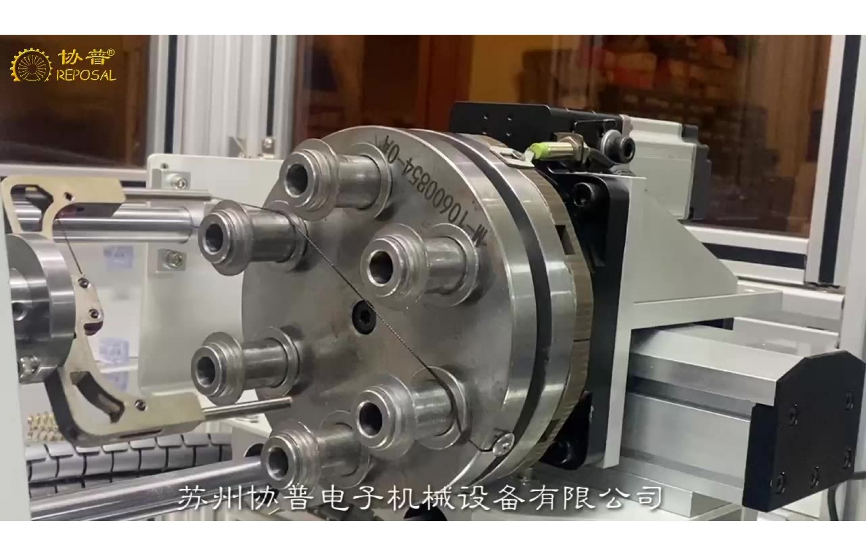
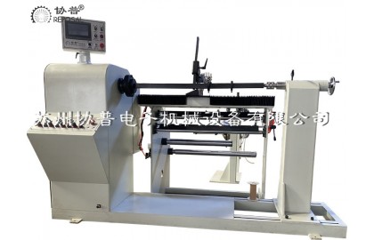
In the manufacture of power transformers, winding the transformer coil is a super important step, you think, the transformer coil is wound more firmly and neatly, the strength of the transformer and the ability to protect against short circuits can be greatly improved. However, most of the current transformer winding machines have to rely on manual extra sorting of the coil, the entire equipment is low in automation, and the production efficiency is not high, so the development of an excellent large transformer winding machine is a crucial thing for our company.
![]()
We have studied the main shaft technology of transformer winding machine, the relationship between compaction force and winding quality, and the control of compaction force. According to the principle and process flow of transformer winding, we put forward a whole design scheme of large transformer winding machine, including mechanical structure and electrical control. Mechanically, we simplify the complex structure of traditional transformer winders. In terms of electrical control, we ensure the stability of the motor when it starts and stops, and ensure that the winding coil is evenly tightened during the winding process. For the core parts of the transformer winding machine, spindle system and pressing device, we have calculated and selected the types and parameters. With the compaction device, we are able to provide real-time axial and radial compaction forces during the winding process of the transformer winding, which is very effective for improving the tightness of the winding.
The static analysis of the radial compaction device of the winding machine is also carried out by using finite element method, and the structure optimization is carried out according to the analysis results. We find that as the number of layers and turns of the winding increases, the required axial and radial compression forces change accordingly. By analyzing the experimental data, we find that there is a maximum value and a minimum value in the range of quality requirements, and it is the most reasonable choice to make the compression force approximately proportional to the number of layers and the number of turns.
The large transformer winding machine developed by our company has been preliminatively debugged and put into the market. After testing, the performance parameters of this transformer winding machine are in line with the design requirements, and the operation is stable and efficient. It can be wound to make a tight and regular transformer winding coil, and has been fully recognized by the market.
As a power grid equipment, power transformer converts voltage through the electromagnetic induction between the winding coils of the transformer. With the continuous development of the market, higher requirements are put forward for the manufacturing level of transformers, and the market needs more energy-saving and efficient transformers. Therefore, the optimization of the transformer manufacturing process is particularly critical. Quality and performance depend on the process equipment. The technical level of the transformer winding machine directly reflects the manufacturing level of the transformer. Therefore, accelerating the development of transformer winding machine is an important guarantee to improve the performance of transformer.
![]()
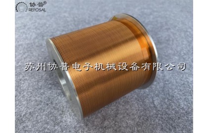
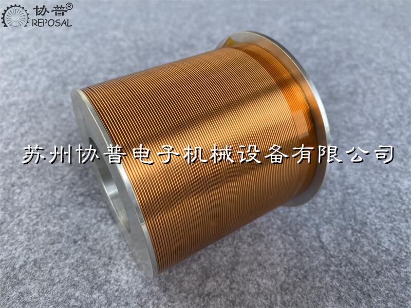
The winding coil of the transformer is the core component of the transformer and constitutes the electromagnetic induction part of the transformer. It generally includes high voltage winding and low voltage winding, respectively connected to the high voltage grid and low voltage grid. The winding of large power transformers usually adopts concentric winding, that is, the high and low voltage transformer winding coils are centrally set on the core column. The manufacture of transformer winding is the core process of transformer, and its quality plays a crucial role in the performance of transformer, affecting the appearance of transformer size, weight, mechanical properties, insulation and heat resistance and other important indicators.
In the past, the production of transformer winding coils relied on manual, and workers had to wind insulated wires manually to the winding die frame in accordance with the process requirements. Turns calculation also have to rely on manual, this old-fashioned method is inefficient, and because the worker's skills are not strong enough, the quality of the winding coil is poor, the number of turns may be miscalculated or missed, and ultimately lead to the finished winding coil performance can not be guaranteed. Later appeared semi-automatic transformer winding machine, which is driven by the motor to rotate the spindle to wind the transformer winding coil, although it improves the production efficiency, but the wiring work still has to rely on manual, only suitable for flat winding transformer winding coil winding, and winding head winding, welding and other operations must still be completed manually, so the product quality is not stable.
Later, with the emergence of TTL logic gate circuits, in the mid-1970s, with the development of CMOS technology, various types of equipment program control a large number of applications of digital integrated circuits, Western countries and Japan and other industrial powers have emerged CNC winding mechanism manufacturing industry. These CNC transformer winding machines represent the advanced level of winding mechanism manufacturing technology, especially the winding equipment produced in Japan, Italy, the United States and Germany is the leading technology.
Now the transformer winding machine as the core parts of the transformer production equipment, the market demand is very large, and the transformer manufacturing enterprises at home and abroad attach great importance to the development and application of advanced technology of transformer winding machine. Domestic transformer winding machine production enterprises are small, insufficient technical reserves, limited research and development funds, so there is still a big gap compared with foreign advanced products, the market share is low, unable to compete with foreign countries. To solve the key technical problems of transformer winding machine is the key to improve the quality of domestic winding equipment and enhance the market competitiveness. In order to meet the demand of transformer manufacturers for high quality and low price winding equipment, especially large transformer winding machine, on the basis of learning from foreign advanced experience, combined with domestic research results, the development of large transformer winding machine has important significance and practical value.
REPOSAL® winding machine has successfully provided competitive solutions to the electron microscopy winding process
The main components of scanning electron microscope are electron optics system, signal collection and processing system, vacuum system, image processing display and recording system, power system and computer control system. The core part is the electron optical system, which is mainly composed of electron gun, electromagnetic condenser, diaphragm, scanning system, astigator, objective lens and various centering coils.
Reposal® winding machine As a professional supplier of precision winding solutions, we focus on the electromagnetic condenser, objective and astigmatic, because the main components are enamoured wire windings, and the precision and consistency of the windings are highly related to the image quality of the scanning electron microscope.
Electromagnetic lens coil.
The electromagnetic lens is mainly used to restrain the electron beam and it can be regarded as a convex lens in optics. Because the electron beam in a rotating symmetric magnetic field will be subjected to the Lorentz force, resulting in a focusing effect. Therefore, the quality of the enamelled wire winding coil that can generate this rotationally symmetric rather than uniform magnetic field and make the electron beam focus imaging is very important.
The enamelled wire winding coil in the magnetic lens, when the current passes through the coil, the pole shoe is magnetized, and a magnetic field is established in the heart cavity, producing a focusing effect on the electron beam. There are two kinds of enamelled wire winding in the magnetic lens, namely, the enamelled wire winding of the condenser and the enamelled wire winding of the objective lens. The lens near the electron gun is the enamelled wire winding of the condenser, while the one near the sample is the enamelled wire winding of the objective lens. General condenser is the high excitation lens enamelled wire winding, high excitation lens enamelled wire winding has many turns, a cylindrical multi-layer arrangement, requires good rotation symmetry
Study on the control of the speed curve of the coiling machine for precision coiling machine
Your factory is using a traditional winding machine, your wire machine structure is reasonable, high mechanical accuracy, the motor is also used a big brand of motor, but in the winding of precision coils, there will be a high defect rate, you carefully analyze before improving various factors - equipment structure, processing accuracy, tooling accuracy, skeleton accuracy, enamel wire quality, tension control, etc. But it still doesn't solve the problem. But to tell you that it's not just a hardware problem, but an algorithm problem, may surprise you. Because in your opinion, every time the spool is transferred, the spool has a corresponding response, but in fact, you may not have considered that in the winding process of the precision coil, the wire guide pin is connected at both ends of the coil, and the sudden change in speed may cause the coil to cross the line and be raised. These defects can degrade the performance of the coil.
To solve this problem, we propose an acceleration and deceleration method based on 5-segment S-curve. The algorithm uses linear acceleration or deceleration at the end and end of the line motion control to help reduce coil defects. We first verify the feasibility of the algorithm by using ADAMS software. The software simulates the motion of the precision winding coil and obtains the velocity curve and displacement curve during the motion. Later, the experimental results show that the method of adopting S-curve in the alignment speed control can reduce the coil defect by up to 50%. This shows that the 5-section S-curve motion control algorithm is a promising method to improve the precision and efficiency of the winding process of electric precision coils. By using this algorithm, coil manufacturers can reduce the risk of coil defects and improve coil performance.
Winding machine is a special production equipment for precision winding coils. They can be divided into stator winding machine, flying fork winding machine, ring winding machine and flat winding machine according to the working mode and object. Different types of equipment are suitable for the production of different objects. For example, the stator winding machine is mainly used to produce motor stator coils, while the parallel winding machine is used to produce electromagnetic switching coils.
Ordinary algorithm of parallel winding machine in the production of precision winding coil products, although our mechanical structure, parts processing accuracy has been done very well, but often there is a problem of low wiring accuracy. In the process of winding a line coil, there are two main movements, one is the rotating movement of the skeleton, which is called winding movement, and the other is the translation movement of the guide needle, which is called wiring movement, and wiring transport is matched with winding movement. After years of technical accumulation, we analyze that the leading role in the alignment accuracy is the alignment movement of the guide needle. Therefore, if you want to improve the alignment accuracy of the coil, you need to optimize the alignment movement of the guide pin.
In fact, we have always believed that the winding machine is equivalent to the lathe in the electrical industry, its importance is self-evident, so for its accuracy, there have been many experts and scholars to study this.
Some people studied the mathematical model of precise alignment based on axial pressure compensation around the axis in the process of alignment. The axial pressure was used to improve the alignment regularity of the coil, and the mathematical model was established according to the analysis of the end point of the coil alignment, which improved the alignment accuracy of the coil.
Some people use the 5-section S-curve control algorithm and the 7-section S-curve control algorithm respectively in the research. In motion control, the 7-section S-curve is more complicated than the 5-section S-curve control. This method has achieved more results in the field of CNC machining, but it is not mature in the field of winding machine.
The tension instability caused by the friction between the enamelled wire and the conductor nozzle during coil winding has been studied, which leads to the uneven wiring of the coil and the breakage of the enamelled wire.
Some people have studied the low efficiency of the winding machine in the traditional winding control because of the inertia error in the process of the winding machine. Instead, the servo motion wiring and the inertia error supplement are used to improve the control efficiency of the winding machine.
PLC control is commonly used in the winding machine wiring control system, through PLC control servo motor can realize the winding machine wiring control, both PLC control stability and high precision servo motor advantages. However, there is a sudden impact of guide pin speed in the coil alignment of parallel winding machine, so it is necessary to further optimize the change of guide pin running speed to improve product quality and the smoothness of wire alignment speed. The S-curve algorithm is a kind of smooth transition of speed in the process of motion, which is often used in machining to solve the problem of breaking the tool caused by speed impact and improve the precision of machining products. In the winding machine, the speed of the guide needle can be changed into an arc smooth transition by controlling the movement track of the guide needle, improving the alignment accuracy and product quality.
To sum up, an algorithm based on 5-segment S-curve motion control is proposed to solve the problem of velocity shock in the process of coil alignment by analyzing the law of coil alignment. ADAMS software is used to simulate the trajectory of the guide pin to verify the feasibility of the algorithm. And the application of the example proves that the 5-section S-shaped curve can effectively solve the phenomenon of crossing and protruding in the process of winding, and improve the precision of winding.
Coil wiring principle
The winding method is flat winding, that is, the enameled wire moves synchronously with the guide pin and always keeps perpendicular to the skeleton during winding. The frame is driven by the winding motor with the guide needle movement, the enameled wire is wound on the skeleton, in which the guide needle is located in the wiring arrangement mechanism and the winding mechanism are two independent mechanisms. The winding mechanism is divided into three stages according to the motion process of the guide pin, namely acceleration and deceleration stage, uniform speed stage and end point return stage. The acceleration and deceleration stage can be divided into two parts: acceleration stage and deceleration stage. In the early stage of the alignment movement, the guide pin speed from zero to uniform speed belongs to the acceleration stage. At the end of the alignment movement, the process of decelerating until the speed reaches zero is a deceleration stage. The middle constant velocity stage is the constant velocity motion stage of the guiding needle. The terminal reentry stage is a process in which the guide needle accelerates backward again after slowing down and stopping. Here we explain:
Acceleration and deceleration stage
In order to arrange the lines evenly, the two movements of guide pin movement and skeleton rotation should meet certain coordination relations during acceleration and deceleration stage. The time for the guide needle to move one diametral width distance must be equal to the time for the skeleton to rotate once, that is, the guide needle to move just one diametral distance when the skeleton rotates once.
REPOSAL ® winding machine has successfully realized the coil preparation process of the frameless capillary magnetic liquid acceleration sensor
In particular, the non-magnetic material in the magnetic liquid will be subjected to a magnetic field force in the non-uniform magnetic field, which makes many magnetic liquid acceleration sensors can be designed based on this characteristic.
These characteristics make the magnetic liquid acceleration sensor has many advantages compared with the traditional acceleration sensor, such as no wear, high sensitivity and simple structure.
However, most of the existing magnetic liquid acceleration sensors use solid mass blocks as non-magnetic substances, and use coils to detect changes in inductance under different accelerations to obtain output signals. However, its disadvantage is that it leads to complex magnetic circuit and poor sensor stability.
A new solution emerged -- the capillary magnetic liquid acceleration sensor, good stability, simple magnetic circuit, accurate and reliable measurement results and long service life.
REPOSAL® winding machine wire guided missile fiber winding forming technology has made a new breakthrough
REPOSAL ® winding machine wire guided missile fiber winding forming technology has made a new breakthrough
Fiber optic guidance of wire-guided missile is a closed-loop guidance and control of controlled missile by bidirectional transmission of information and control signals between missile and launcher using special fiber optics.
Fiber optic guidance belongs to the wire guidance of remote control guidance, its advantages are not only high precision, strong anti-interference ability, can be equipped with optical cable shaft, micro camera, missile launch tail will release fiber, can control the missile and obtain target information.
The winding and release technology of optical fiber is a key technology of optical fiber guidance. At present, we have not realized automatic production in the production of optical fiber winding in our country, so we rely on the winding technical personnel's proficiency very high. The cross-turns working procedure of the winding process is still mainly manual operation, low production efficiency, high error probability and low consistency.
In addition to other ways to solve the high speed release of optical fiber, an important way is to ensure the smooth release of optical fiber through optical fiber winding. Optical fiber winding technology is the requirement of the pointer to the optical fiber guided missile and the technology of winding the optical fiber on the spool. In view of the unique properties of optical fiber and the special use of optical fiber guided missile, optical fiber winding becomes a complicated technical problem. In the process of automatic winding, the technical difficulties related to the properties of optical fiber are as follows:
REPOSAL® Winder Releases Coded Teach Winder Control System
REPOSAL® Winding Machine Releases Code-Type Teaching Winding Machine Control System
REPOSAL® Winding Machine, a domestic coil intelligent manufacturing solution provider, has launched its new generation of code programming teaching type winding machine control system that is more open, intelligent and highly autonomous for coil winding enterprises - REPOSAL® Winding machine SP500-R5 system. Compared with the traditional dialog-type winding machine control system, the SP500-R5 system has achieved major breakthroughs in operation logic, technical architecture, and function implementation. Features.
The SP500-R5 system adheres to the concept of "openness and intelligence". Based on the functions of the traditional dialog-based winding machine control system, it integrates the actual needs of the winding factory, and is committed to realizing the coil winding process programming process from the traditional parameter dialog. A major innovation and upgrade from control to code teaching programming.